SECTION 2, Page 13SJ 600, 800 & 1000 Series
122883AH
May 2002
2
SECTION 2
OPERATION
Operating Controls Identification
The following descriptions are for identification,
explanation and locating purposes only. A qualified
operator MUST read and completely understand
these descriptions before operating this work
platform. Procedures for operating this work platform
are detailed in the “OPERATING PROCEDURES”
section. Both standard and optional controls are
identified in this section. Therefore, some controls
may be included that are not furnished on your work
platform.
Base Controls
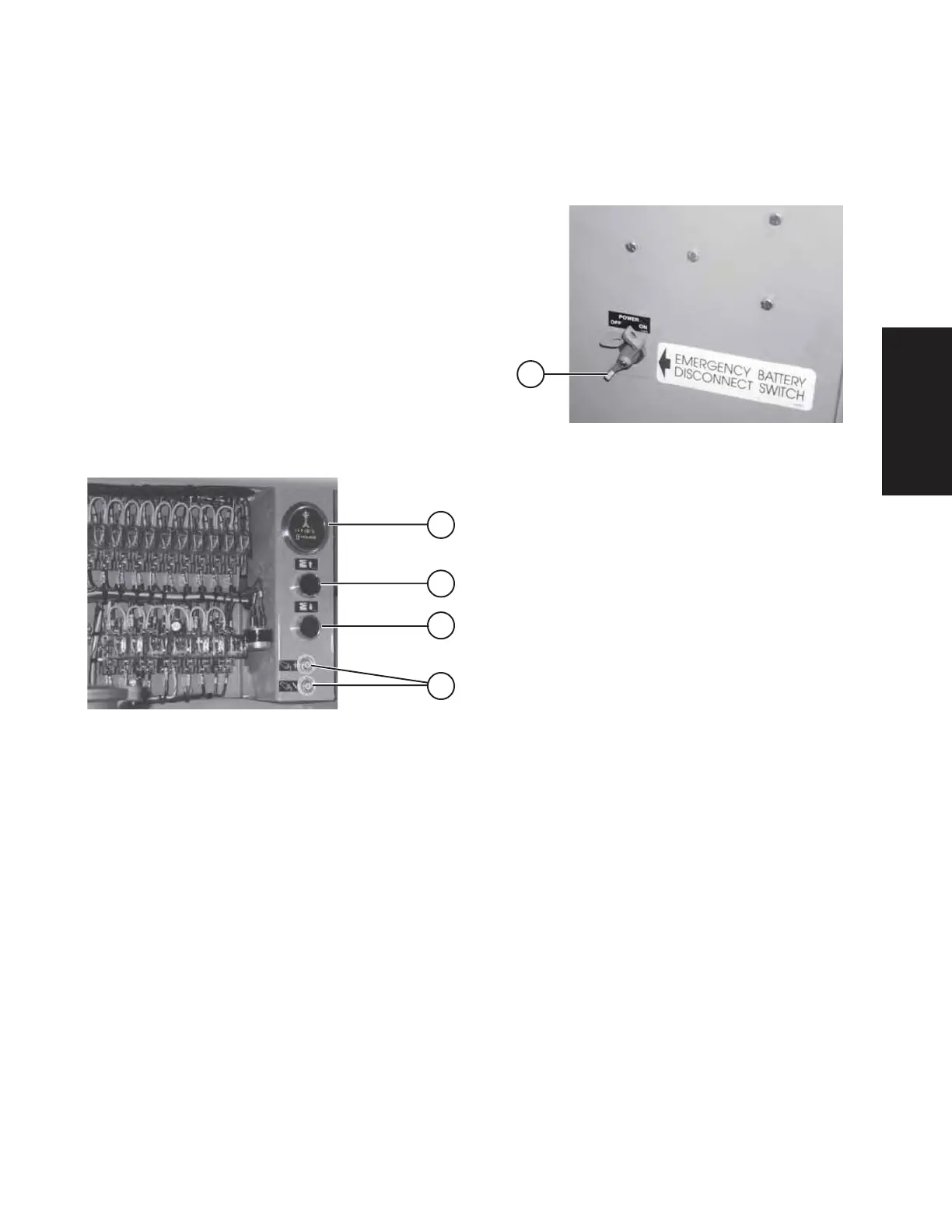
Electrical Panel
Figure 2-1. Electrical Panel
Electrical Panel - This control station is located in the
Hydraulic/Electric Side Cabinet. It contains the
following controls:
1. Up Push-Button Switch - This push-button switch
will raise the platform to desired height.
2. Down Push-Button Switch - This push-button
switch will lower the platform to desired height.
3. Hour meter - This gauge records engine running
time.
4. 20 Amp Circuit Breaker Resets - In the event of
a power overload or positive circuit grounding, circuit
breaker will pop out.
Emergency Battery Disconnect Switch
Figure 2-2. Emergency Battery Disconnect Switch
1. Emergency Battery Disconnect Switch Located
at the front of the Hydraulic/Electric Side Cabinet, this
switch when in the “OFF” position, disconnects power
to all circuits. Switch MUST be in “ON” position to
operate any circuit.
2
1
4
3
1
 Loading...