Assembly & Operation Manual
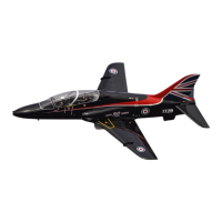
TAIL PIPE
Dril holes in mounting lugs of tail pipe.
Make 90 degree bend in each mounting lug.
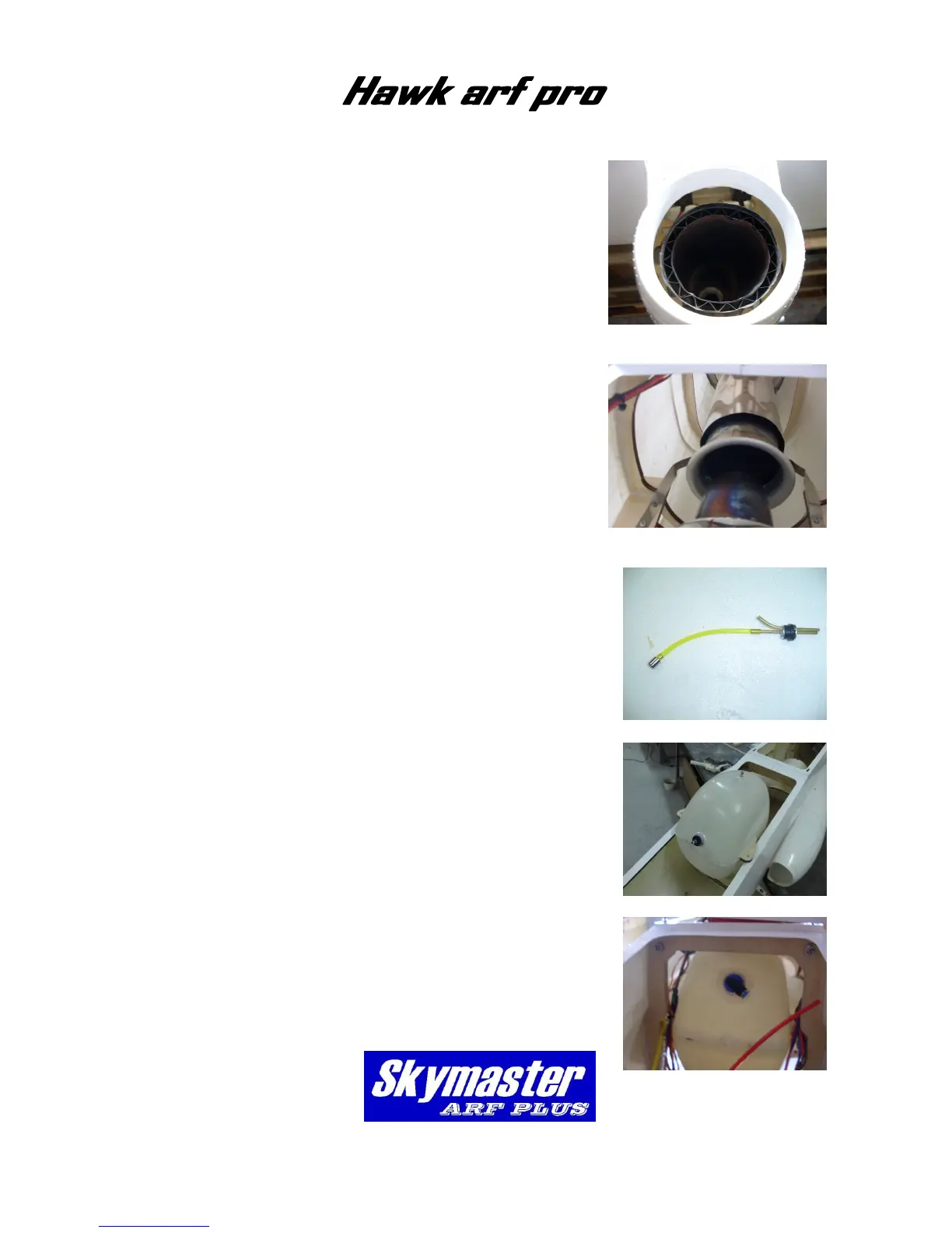
Slide tail pipe through hatch into position. Note: The
rear of pipe must just exit the rear former by 10mm.
Mark location of screws on turbine rail.
Dril pilot holes for self tap screws.
Secure pipe in position and glue end of pipe with sili-
con glue to former.
Glue bellmouth with silicon glue.
Photo 36
Photo 37
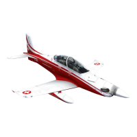
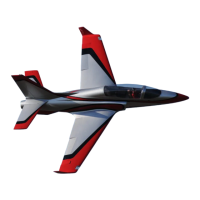
FUEL CELL
Rinse the fuel tank and check for leaks.
Make up fuel line clunk. Make sure clunk moves freely
and reaches all corners of inside of tank.
Fit to tank. Mark pipes for “inlet” and “outlet”.
Install tank by screwing tank to tank mount.
Plumb tanks using diagram on next page.
Fill tanks and check for leaks.
Drain tanks with fuel pump and check no air bubbles in
system until last drop is drained. A good plumbing
will secure good turbine operation.
NOTE: In addition you can use BVM tank fitting kit. Such fit-
tings are shown in picture 37.
P-19
Photo 38
Photo 39
Photo 40