SYSTEM CHECK
MILLIVOLT VALVES AND ELECTRONIC SPARK IGNITION SYSTEMS
Light your gas appliance following the lighting instructions that came with the appliance. Confirm that the pilot flame is on; it must be in
operation for the main gas valve to operate.
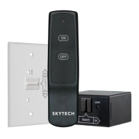
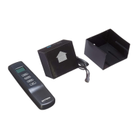
• Slide the 3-position button on the remote receiver to the ON position. On millivolt systems the main gas flame (i.e., the fire)
should ignite. On Electronic ignition systems the spark electrode should begin sparking to ignite the pilot (the pilot may ignite
after only one spark). After the pilot flame is lit, the main gas valve should open and the main gas flame should ignite.
• Slide the button to OFF. On millivolt systems the flame should extinguish (the pilot flame will remain on). On electronic ignition
systems the main gas flame and pilot flame should BOTH extinguish.
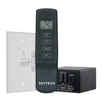
• Slide the button to REMOTE (the center position), and then press the ON button on the transmitter to change the system to
ON. The main gas flame should ignite. On Electronic ignition systems the spark electrode should begin sparking to ignite the
pilot (the pilot may ignite after only one spark). After the pilot flame is lit, the main gas valve should open and the main gas
flame should ignite.
GENERAL INFORMATION
CODE SETTING
CAUTION: All units are shipped from the factory with the code switch pre-set to the same
codes. These switches must be re-set to different codes during installation to prevent interference
from another remote.
Each transmitter can use one of 255 set able security codes. It WILL be necessary to
set the transmitter and receiver code switches to a matching security code upon initial
use. If a replacement transmitter or receiver is purchased from your dealer or the factory, the
code switches must be set to match the receiver transmitter code switches. When setting the
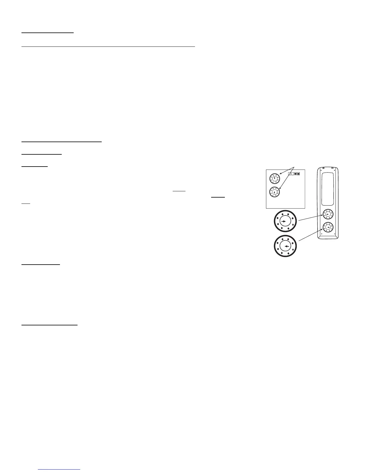
code switches set the A through P switch on the transmitter to the same setting as the A
through P switch on the receiver. Then set the 1 through 16 switch on the transmitter
to the same setting as the 1 through 16 switch on the receiver.
Note: A small screwdriver can be used to change these code switches.
Note: The figure to the right showing the code switches on the transmitter and
receiver.
BATTERY LIFE
Life expectancy of the alkaline batteries in the transmitter should be at least 12 months. Check and replace all batteries annually.
When the transmitter no longer operates the remote receiver from a distance it did previously (i.e., the transmitter’s range has
decreased) or the remote receiver doe not function at all, the batteries should be checked. It is important that the remote receiver
batteries are fully charged and provides continuous output voltage of a least 5.3 volts. The length of the wire between the remote
receiver and gas valve directly affects the operating performance of the remote system. The longer the wire, the more battery power is
required to deliver signals between the remote receiver and the gas valve. Recommended length is no longer than 20 feet. The
transmitter should operate with as little as 2.5 volts battery power.
TROUBLE SHOOTING
If you encounter problems with your fireplace system, the problem may be with the fireplace itself or it could be with the remote.
Review the fireplace manufacturer’s operation manual to make sure all connections are properly made. Then check the operation of
the remote in the following manner:
• Make sure the batteries are correctly installed in the RECEIVER. One reversed battery will keep receiver from operating properly.
• Check battery in Transmitter to make sure it is installed with the (+) side up.
• Check the code settings on the transmitter and receiver that they are matched settings.
• Be sure RECEIVER and Transmitter is within 20-25-foot operating range.
• Keep RECEIVER from temperatures exceeding 130
0
F. Battery life shortened when ambient temperatures are above 130
0
F.
• If RECEIVER is installed in tightly enclosed metal surround, the operating distance will be shortened.