WIRING ELECTRONIC SPARK IGNITIONS
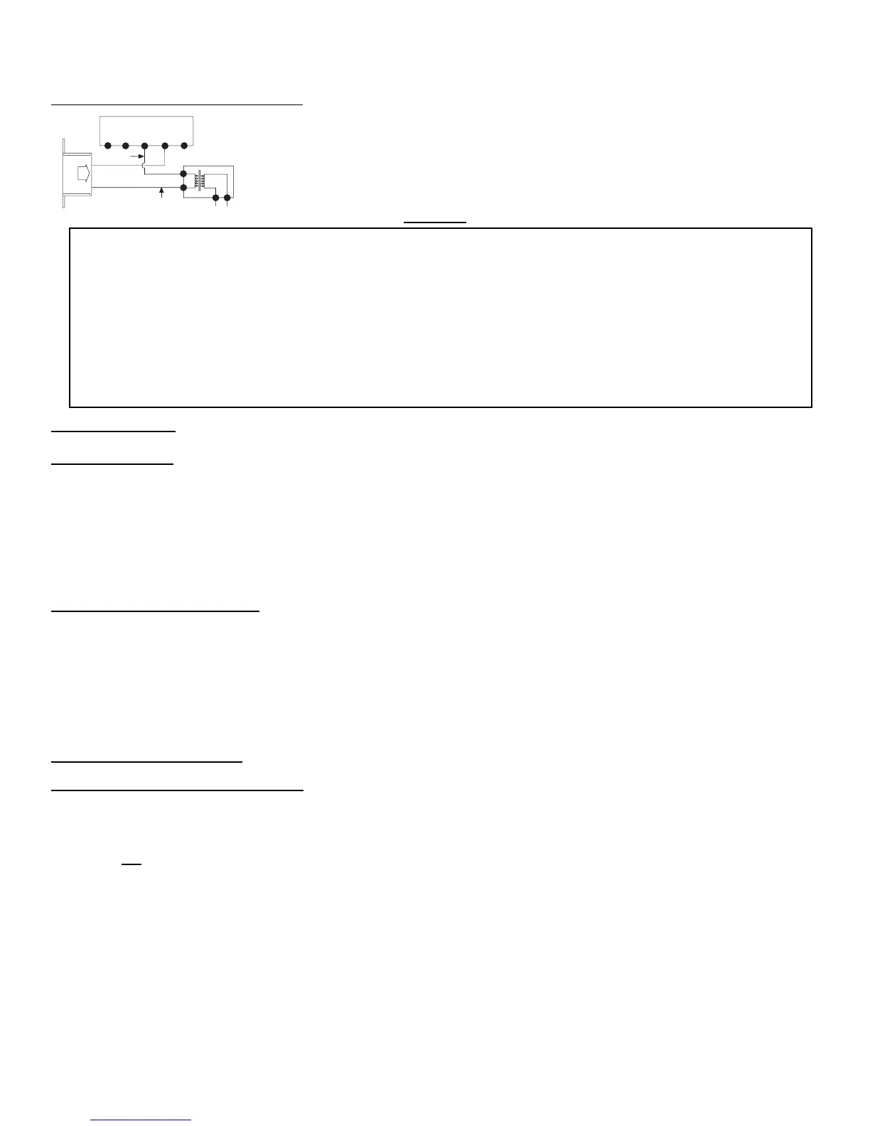
The remote control receiver can be connected, in series, to a 24VAC transformer to the TR
(transformer) terminal on the ELECTRONIC MODULE. Connect the hot wire from the 24VAC
transformer to either of the wire terminals on the remote receiver. Connect another wire (included)
between the other receiver wire terminal and the TH (thermostat) terminal on the ELECTRONIC
MODULE.
WARNING
SYSTEM CHECK
MILLIVOLT VALVES
Light your gas appliance following the lighting instructions that came with the appliance. Confirm that the pilot flame is on; it must be in
operation for the main gas valve to operate.
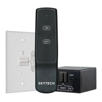
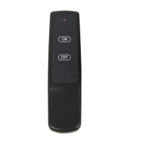
• Slide the 3-position button on the remote receiver to the ON position. The main gas flame (i.e., the fire) should ignite.
• Slide the button to OFF. The flame should extinguish (the pilot flame will remain on).
• Slide the button to REMOTE (the center position), then press the ON button on the transmitter to change the system to ON. The
main gas flame should ignite.
ELECTRONIC IGNITION SYSTEMS
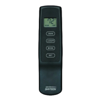
• Slide the 3-position button on the remote receiver to the ON position. The spark electrode should begin sparking to ignite the pilot
(the pilot may ignite after only one spark). After the pilot flame is lit, the main gas valve should open and the main gas flame
should ignite.
• Slide the button to OFF. The main gas flame and pilot flame should BOTH extinguish.
• Slide the button to REMOTE (the center position), then press the ON button on the transmitter to change the system to ON. The
spark electrode should begin sparking to ignite the pilot. After the pilot is lit, the main gas valve should open and the main gas
flame should ignite.
GENERAL INFORMATION
LEARNING TRANSMITTER TO RECEIVER
Each transmitter uses a unique security code. It will be necessary to press the LEARN button on the receiver to accept the transmitter
security code upon initial use, if batteries are replaced, or if a replacement transmitter is purchased from your dealer or the factory. In
order for the receiver to accept the transmitter security code, be sure the slide button on the receiver is in the REMOTE position; the
receiver will not LEARN if the slide switch is in the ON or OFF position. The LEARN button in located on the front face of the receiver;
inside the small hole labeled LEARN. Using a small screwdriver or end of a paperclip gently press and release the black LEARN button
inside the hole. When you release the LEARN button the receiver will emit an audible “beep”. After the receiver emits the beep press
the transmitter ON button and release. The receiver will emit several beeps indicating that the transmitter’s code has been accepted
into the receiver.
The microprocessor that controls the security code matching procedure is controlled by a timing function. If you are unsuccessful in
matching the security code on the first attempt, wait 1-2 minutes before trying again – this delay allows the microprocessor to reset its
timer circuitry – and try up to two or three more times.
This remote control system must be installed exactly as outlined in these instructions. Read all instructions completely before
attempting installation. Follow instructions carefully during installation. Any modifications of the SKYTECH remote control or
any of its components will void the warranty and may be pose a fire hazard.
Do not connect any gas valve or electronic module directly to 110-120VAC power. Consult gas appliance manufacturer’s
instructions and wiring schematics for proper placement of all wires. All electronic modules are to be wired to manufacturer’s
specifications.
The following wiring diagrams are for illustration purpose only. Follow instructions from manufacturer of gas valve and/or
electronic module for correct wiring procedures. Improper installation of electric components can cause damage to electronic
module, gas valve and remote receiver.