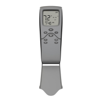
Skytech: Smart Batt III
REV. 5-20-22 Page 4
WIRING INSTRUCTIONS
A qualified electrician or a gas technician who is familiar with the gas appliance and gas valves that will be operated by
this remote should install the remote control system. Incorrect wiring connections WILL cause damage to the gas valve
or electronic module operating the gas appliance and may also damage the remote receiver.
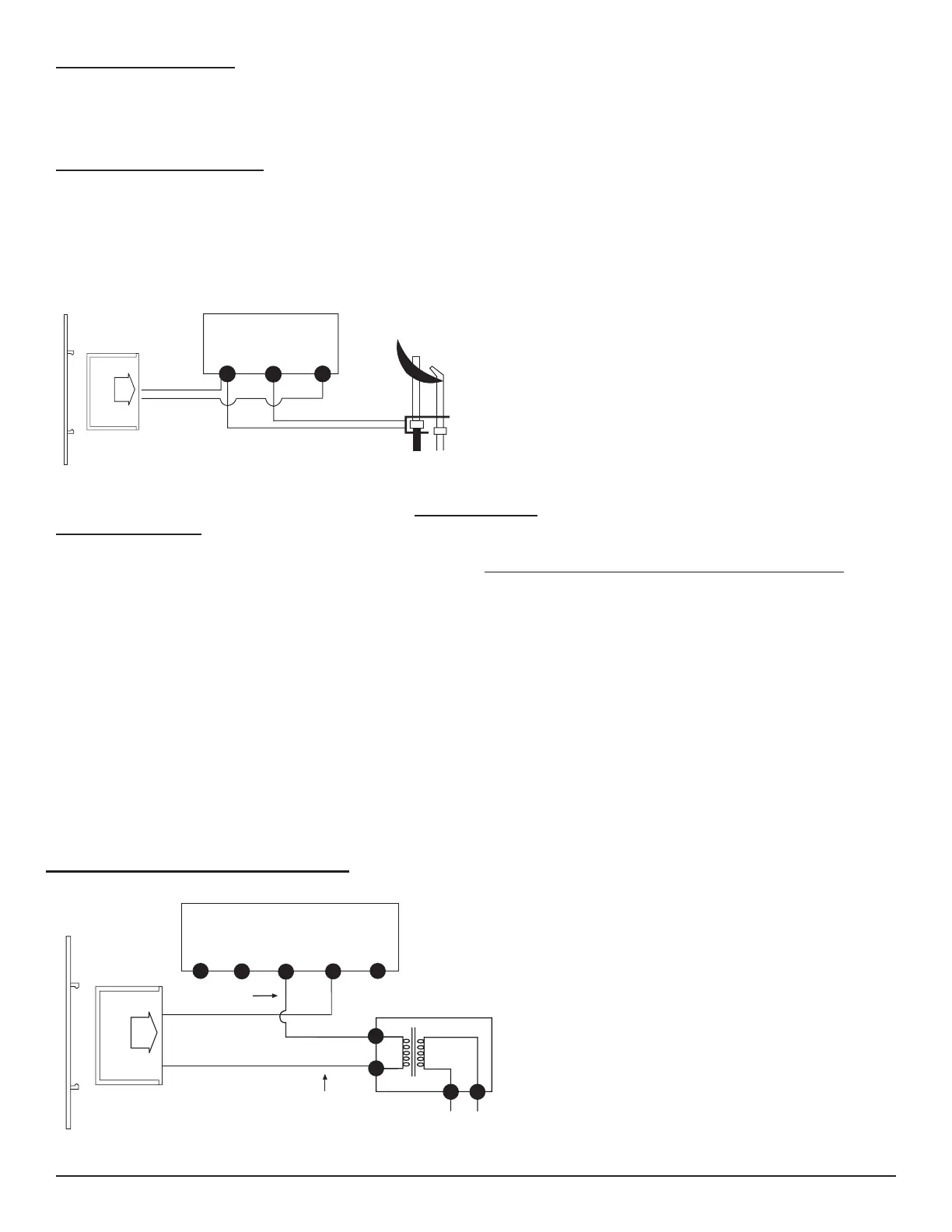
WIRING MILLIVOLT VALVES
The remote receiver is connected to the millivolt valve using the TH (thermostat) terminals on the terminal block on the
millivolt gas valve. Connect 18 gauge solid or stranded wires from the remote receiver to the gas valve.
Operation of the remote receiver is similar to that of a
thermostat in that both turn the gas valve ON and OFF based
on input signals. A thermostat’s input signals are different
temperatures. The remote receiver’s input signals come from
the transmitter.
Connect each of the two wires leading from the TH terminals
on the millivolt gas valve to either of the two wire terminals on
the remote receiver. Normally it does not matter which wires
go to which terminal.
WIRING ELECTRONIC SPARK IGNITIONS
The remote control receiver can be connected, in
series, to a 24VAC transformer to the TR (transformer)
terminal on the ELECTRONIC MODULE. Connect
the hot wire from the 24VAC transformer to either of
the wire terminals on the remote receiver. Connect
another wire (not included) between the other receiver
wire terminal and the TH (thermostat) terminal on the
ELECTRONIC MODULE.
SYSTEM CHECK
MILLIVOLT VALVES
Light your gas appliance following the lighting instructions that came with the appliance. Confirm that the pilot flame is ON;
it must be in operation for the main gas valve to operate. Learn the transmitter to the receiver. See next page.
• Slide the 3-position button on the remote receiver to the ON position. The main gas flame (i.e., the fire) should ignite. •
Slide the button to OFF. The flame should extinguish (the pilot flame will remain ON).
• Slide the button to REMOTE (the center position), and then press the ON button on the transmitter to turn the system to
ON. The main gas flame should ignite.
• Press the OFF button on the transmitter to turn the system to OFF. The flame should extinguish (the pilot flame will
remain on).
• Press the MODE button on the transmitter to change the system to THERMO. Advance the SET temperature on
the transmitter to a temperature of a least 2°F (1°C) above the ROOM temperature displayed on the LCD screen.
With this manual setting, the normal thermostatic cycle is overridden and the system flame will ignite. Set the SET
temperature to at least 2°F (1°C) below the room temperature and the system flame will extinguish in a few seconds.
Thereafter, it should continue to cycle ON and OFF thermostatically approximately every two minutes as the ROOM
temperature changes, but only when the temperature differential between ROOM and SET temperatures differ at least
2°F (1°C). The 2° F differential is the factory setting.
ON MILLIVOLT
GAS VALVES
TH
TP
TP
TH
THERMOPILE/
PILOT LIGHT
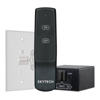
REMOTE
RECEIVER
ELECTRONIC MODULE
TR
TH
REMOTE
RECEIVER
neutral wire
24VAC
hot wire
120VAC
110/24VAC
Transformer

 Loading...