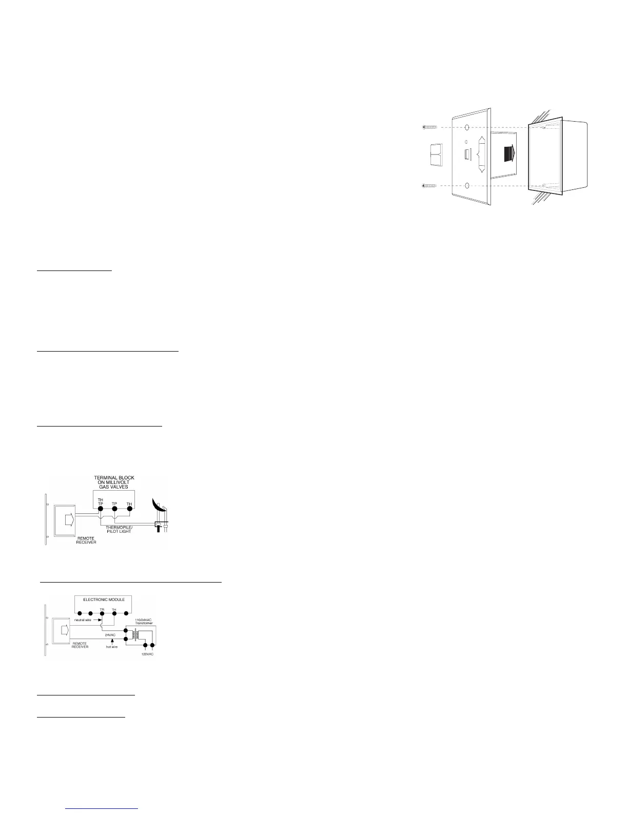
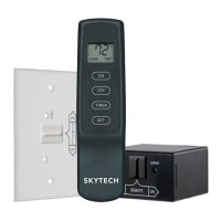
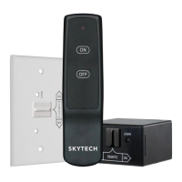
3. Position the wall cover plate so the word ON is facing up.
4. Install the remote receiver into the plastic switch box using the two
long screws provided. Push the slide Button over the receiver slide
switch only after making sure the remote receiver has LEARNED the
transmitter’s security code (see LEARNING TRANSMITTER TO
RECEIVER). NOTE: Slide button covers the Learn hole when properly
installed.
NOTE: The remote receiver will only respond to the transmitter when the 3-position
slide button on the remote receiver is in the REMOTE position. If the system does
not
respond to the battery transmitter on initial use, see LEARNING TRANSMITTER TO
RECEIVER,
and recheck battery positions in the remote receiver.
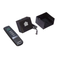
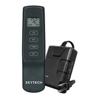
HEARTH MOUNT
The remote receiver can be placed on the fireplace hearth or under the fireplace, behind the control access panel. Position where the
ambient temperature inside the receiver case does not exceed 130
0
F.
NOTE: Black Slide Button is used for Hearth Mount applications.
WIRING INSTRUCTIONS
A qualified electrician or a gas technician who is familiar with the gas appliance and gas valves that will be operated by this remote
should install the remote control system. Incorrect wiring connections WILL cause damage to the gas valve or electronic module
operating the gas appliance and may also damage the remote receiver.
WIRING MILLIVOLT VALVES
The remote receiver is connected to the millivolt valve using the TH (thermostat) terminals on the terminal block on the millivolt gas
valve. Connect 18 gauge stranded or solid wires from the remote receiver to the gas valve.
Operation of the remote receiver is similar to that of a thermostat in that both turn the gas valve on
and off based on input signals. A thermostat’s input signals are different temperatures. The remote
receiver’s input signals come from the transmitter.
Connect each of the two wires leading from the TH and TH/TP terminals on the millivolt gas valve to
either of the two wire terminals on the remote receiver. Normally it does not matter which wires go to
which terminal.
WIRING ELECTRONIC SPARK IGNITIONS
The remote control receiver can be connected, in series, to a 24VAC transformer to the TR
(transformer) terminal on the ELECTRONIC MODULE. Connect the hot wire from the 24VAC
transformer to either of the wire terminals on the remote receiver. Connect another wire (Not included)
between the other receiver wire terminal and the TH (thermostat) terminal on the ELECTRONIC
MODULE.
SYSTEM CHECK
MILLIVOLT VALVES
Light your gas appliance following the lighting instructions that came with the appliance. Confirm that the pilot flame is on; it must be in
operation for the main gas valve to operate.