Do you have a question about the Skytrak 6036 and is the answer not in the manual?
Provides general directions for service and repair procedures, emphasizing safety and reliability.
States that the manual is based on the latest product information and reserves the right to make changes without notice.
Outlines the requirement for mechanics to read and understand the Operation & Safety Manual before operating the machine.
Instructs on the proper use of "Do Not Operate" tags and key removal before maintenance.
Emphasizes compliance with all safety messages and preparedness for accidents, including first-aid and emergency contacts.
Explains the meaning of DANGER, WARNING, and CAUTION signal words used in safety messages.
Provides general safety statements to consider before performing maintenance procedures on the telehandler.
Covers the importance of wearing appropriate personal safety gear for the job.
Details hazards related to lifting equipment, supporting loads, and using hand tools.
Covers general safety practices related to solvents, housekeeping, first aid, and cleanliness.
Outlines hazards related to engine operation, fluid temperatures, pressure, and tire inflation.
Advises checking that all safety decals are present and readable on the machine.
Details on ordering replacement parts and information regarding warranty registration and claims.
Provides technical data for the machine, including travel speeds and hydraulic cylinder performance.
Lists the travel speeds for each transmission gear for different models.
Details the approximate times for various hydraulic cylinder functions.
Provides specifications for the machine's electrical system, including battery details.
Lists engine specifications for different configurations, including horsepower and torque.
Specifies tire sizes, types, ply ratings, fill types, and pressures for various models.
Lists recommended fluids and lubricants for various compartments and systems, including ambient temperature ranges.
Provides capacities for engine oil, fuel tank, cooling system, hydraulic system, and transmission.
Outlines maintenance tasks based on operating hours or time intervals.
Details lubrication points and intervals for different service hours.
Lists JLG part numbers, Loctite equivalents, and ND Industries descriptions for thread locking compounds.
Provides torque values for SAE and Metric fasteners, considering different materials and coatings.
Defines common electrical components referred to in the section.
References electrical system specifications found in Section 2.
Provides critical safety precautions for working with electrical systems.
Details the location and circuits for fuses and relays in the engine compartment and cab harness.
Identifies fuses and relays located in the engine compartment's protective case.
Lists fuses and relays associated with the cab harness for different models.
Provides diagrams of the machine's electrical systems for various configurations and options.
Electrical schematic specific to the operator's cab.
Electrical schematic for the chassis and engine, covering specific horsepower and ULS configurations.
Electrical schematic for the chassis and engine, covering specific horsepower and LS configurations.
Electrical schematic for the chassis and engine, covering the 74 hp (55 kW) configuration.
Electrical schematic for the Cab O/R option specific to Model 10042.
Electrical schematic for the Cab O/R option specific to Model 10054.
Electrical schematic for the HVAC option.
Electrical schematic for the road lighting option.
Electrical schematic for the worklights and beacon option.
Electrical schematic for the telematics option.
Explains the purpose and method for applying dielectric grease to electrical connectors.
Covers the starter motor, circuit checks, and removal/installation procedures.
Provides information on battery inspection, removal, installation, and disconnection/connection.
Details checks for the charging system, including battery cable connections and alternator.
Covers removal, disassembly, inspection, installation, and testing of the windshield wiper motor.
Explains the removal and installation of cab heater controls and the heater/AC system.
Lists and describes various solenoids, sensors, and senders used in the machine's systems.
Details the removal, disassembly, and installation of the coolant level sensor.
Explains how to check transmission solenoid valves for proper function and potential issues.
Covers the removal, inspection, installation, and testing of the transmission temperature sender.
Provides procedures for removing, installing, and adjusting the service brake switch.
Details the removal, disassembly, installation, and testing of the boom angle sensor.
Covers the removal and installation of the boom extend interlock sensor specific to Model 10054.
Explains the testing, removal, and installation of outrigger pressure switches for Model 10054.
Covers the removal and installation of the display monitor and its components.
Details the removal, disassembly, inspection, replacement, and installation of dash switches.
Explains how to access machine and engine data using diagnostic tools.
Describes access levels for the analyzer software and its diagnostic functions.
Lists the data points available through the telematics gateway device.
Provides guidance on fault detection and offboard diagnostics.
Lists fault codes related to various machine systems, including engine, battery, and communications.
Lists engine fault codes, their SPN, FMI, and description for troubleshooting.
Identifies major assemblies of the machine cab and covers for understanding.
Covers cab safety and the location and purpose of the serial number decal.
Details various components within the operator's cab, including steering wheel, pedals, and controls.
Provides procedures for removing and installing the steering wheel.
Covers removal, installation, and testing of the steering column and valve.
Details the removal and installation procedures for the service brake pedal.
Outlines the removal and installation procedures for the throttle pedal.
Provides instructions for removing and installing the hydraulic joystick assembly.
Covers the removal, installation, and testing of auxiliary and frame level lever assemblies.
References Section 9.10 for removal and installation of the windshield wiper motor.
Details the removal and installation of the cab heater assembly.
Covers the removal and installation of the heater and A/C system components.
Provides step-by-step instructions for removing the machine cab, including safety precautions.
Details the procedures for installing the cab onto the machine frame, including alignment and connections.
Identifies and defines components related to axles, drive shafts, wheels, and tires.
Provides general information on drive shaft assemblies, cleaning, and servicing of axles and drive shafts.
Covers axle serial number plates, specifications, internal service, maintenance, and replacement procedures.
Lists common problems with axle assemblies and drive shafts, along with their causes and remedies.
Details drive shaft inspection, maintenance, removal, and installation procedures.
Provides guidelines for selecting replacement tires and procedures for removing and installing wheel and tire assemblies.
Covers brake disc inspection and troubleshooting related to brake engagement and holding power.
Provides instructions and precautions for towing a disabled machine.
Identifies major components of the transmission assembly.
Specifies the location of the transmission serial number plate.
Refers to Section 2 for transmission specifications, oil, and maintenance information.
Provides detailed procedures for transmission removal, inspection, internal repair, and installation.
Lists common transmission problems, their causes, and recommended remedies.
Provides a disclaimer and scope for the engine section, including guidelines for worldwide use and referencing Cummins manuals.
States the location of the engine serial number for correspondence.
Refers to Section 2 for engine, coolant, and oil specifications, and maintenance information.
Covers coolant system pressure cap, thermostat replacement, and radiator/oil cooler removal/installation.
References Section 9 for engine electrical system details, including starter and primary wiring.
Covers diesel fuel, fuel/hydraulic oil tank removal/installation, and DEF system components and maintenance.
Details procedures for removing and installing the exhaust system for different engine configurations.
Provides instructions for removing and installing the air cleaner assembly.
Outlines the procedures for engine removal and installation, including necessary tools and safety precautions.
Details the removal and installation procedures for the isolation coupler.
Identifies and defines hydraulic components referred to in the section.
Provides critical safety precautions for working with hydraulic systems, including fluid hazards and contamination.
Refers to Section 2.2 for hydraulic system specifications.
Covers hydraulic circuits, function pressures, and checking procedures, emphasizing electrical and hydraulic interrelationships.
Outlines general steps for conducting pressure checks and performing adjustments on the hydraulic system.
Details procedures for hydraulic oil reservoir draining, filling, filter replacement, and replacement.
Refers to internal service instructions from the authorized service distributor for pump replacement.
Covers the main control valve, service brake valve, steering orbitrol valve, steer select valve, secondary function manifold, and outrigger valve.
Provides general instructions, pressure checking, and torque specifications for hydraulic cylinders.
Identifies major assemblies of the Stabil-TRAK system for understanding the section.
Identifies components of the boom extend interlock system specifically for Model 10054.
Explains the patented rear axle lock or Stabil-TRAK system and its operating modes.
Describes the machine's operation in Free Pivot, Slow Pivot, and Locked modes, including conditions and effects.
Describes the purpose and function of the boom extend interlock system on Model 10054.
Details the Extend Interlock Mode and Outrigger Interlock Mode operations for Model 10054.
Provides instructions for testing the Stabil-TRAK system's function and proper operation.
Covers electrical circuit operation and troubleshooting for the Stabil-TRAK system on specific models.
Details electrical circuit operation and troubleshooting for Stabil-TRAK and boom interlock systems on Model 10054.
Outlines the procedures for testing the boom/outrigger interlock system.
Describes the hydraulic circuit operation and troubleshooting for various Stabil-TRAK modes and conditions.
Details the hydraulic circuit operation and troubleshooting for the boom extend interlock system.
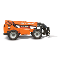
| Power Source | Diesel |
|---|---|
| Maximum Lift Capacity | 6, 000 lbs |
| Maximum Lift Height | 36 ft |
| Engine Power | 74 hp |
| Dimensions | 8 ft |