Stabil-TRAK™ System and Boom Interlock System
10-36
31211015 6036, 6042, 8042, 10042, 10054
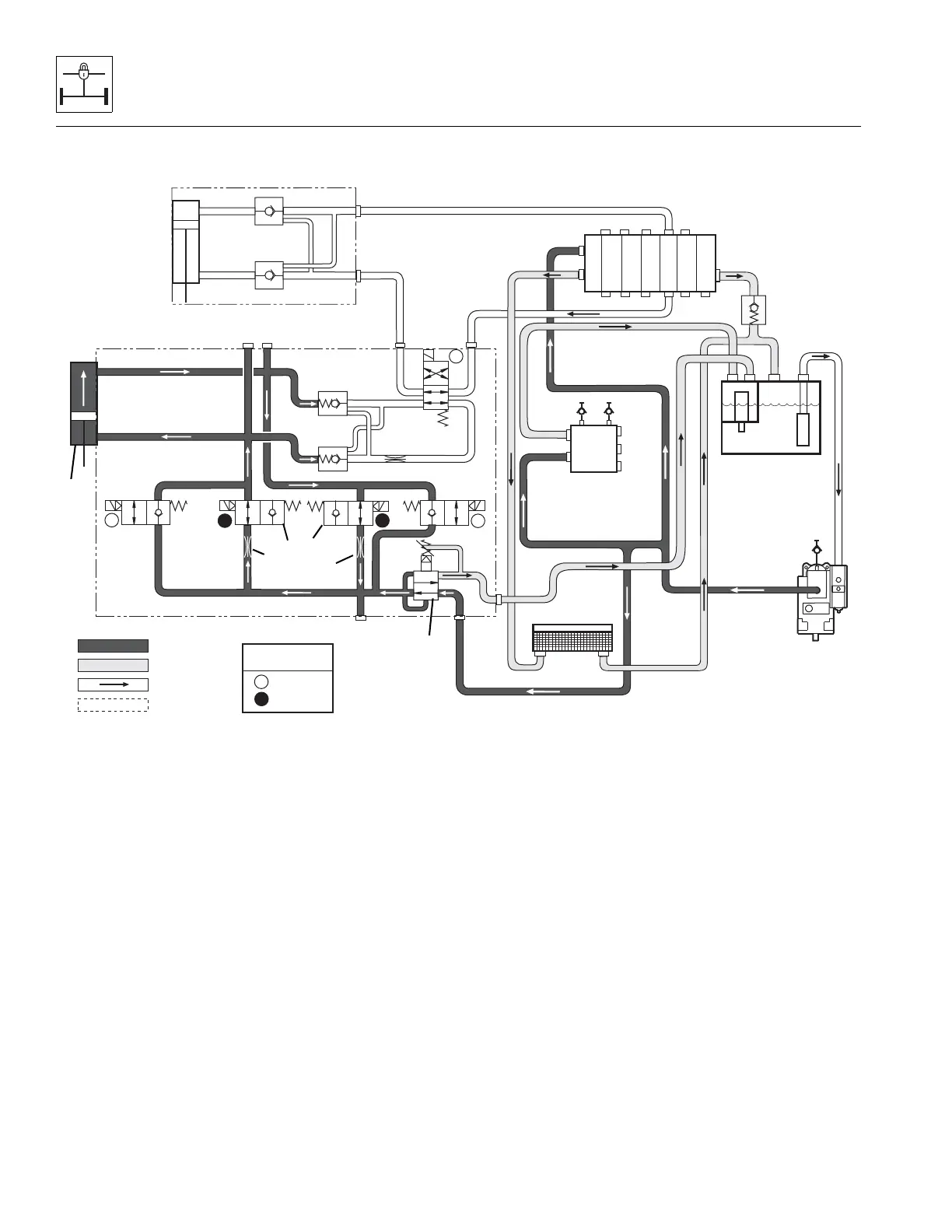
10.11.8 Hydraulic Circuit Operation - SLOW PIVOT Mode, Base Oil Out
Conditions:
• Boom angle is above 40°
• Park brake OFF
• Service brake DISENGAGED
• Travel select lever in (F) FORWARD or (R) REVERSE
position
Operation:
As the boom is raised above 40°, the boom proximity switch
is deactivated causing solenoids 12A and 12B to de-energize
and solenoids 4A and 4B to energize. This allows oil to flow
from the base end of the Stabil-TRAK cylinder (1), through
solenoid-operated valve 4A (2), through a 0.060 inch orifice
(3), through another 0.060 inch orifice (4), then through
solenoid-operated valve 4B (5), to the rod end of the Stabil-
TRAK cylinder.
The 0.060 inch orifices (3 and 4) in solenoid-operated valves
4A and 4B will slow the movement of the rear axle in reaction
to terrain changes. The frame level will react normally in this
mode.
Because of greater volume of oil in base end, extra oil is
returned to the tank through the 100 psi (7 bar) reducing
cartridge (6) in the Stabil-TRAK manifold. Restrictions produce
slow movement, or SLOW PIVOT mode.
MAQ2010
BYPASS
CHECK
VALVE
FTR
P
T
V
Pressure
Suction
Return
Load Sense
G3
G2
G1
4A4B
12B
3
2B
2A
12A
FRAME
LEVEL
CYLINDER
.060 DIA.
.060 DIA.
100 PSI
SOLENOID COIL
STATE
ENERGIZED
DE-ENERGIZED
DE
E
DE
STABIL-TRAK
CYLINDER
E
DE
P
T
BV
JS
PB
PVG
PBG
T
ATTACH TILT
FRAME SWAY
EXT/RET
LIFT/LOWER
AUX
STABIL-TRAK
MANIFOLD
TM
TM
HYDRAULIC
OIL COOLER
HYDRAULIC
RESERVOIR
SECONDARY
FUNCTION
MANIFOLD
MAIN CONTROL
VALVE
T3
P
.030 DIA.
E
DE