Boom
3-39
6036, 6042, 8042, 10042, 10054 31211015
14. Pull the extend chain forward and place over the right
side of the chain sheave (10). Guide the wire and the
threaded clevis under the chain sheave, and between
the top of the third boom section (11) and the second
boom section (12).
15. Have an assistant guide the extend chain into the front
of the boom, while pulling on the wire from the rear of
the boom. Guide the threaded clevis into the hole in the
anchor plate.
16. Assemble the flat washer and locknut to the threaded
clevis. Thread the locknut until the threads are flush
with the top of the nut.
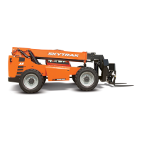
17. Pull the anchor clevis up around the double chain
sheave and position the clevis between the yoke plates.
18. Coat the capscrew with anti-seize compound. Insert the
capscrew through the yoke plates and clevis and secure
in place with a locknut. Tighten securely; but the chain
must pivot freely.
19. Remove the wire from the clevis.
20. Repeat this procedure for the left side extend chain.
21. At the rear of the boom, tighten the two locknuts on the
extend chain clevis’ until the amount of threads
protruding beyond each locknut is the same as the
measurement recorded during removal of the chains.
22. Check and adjust boom chain tension. Refer to
Section 3.7.5, “Boom Chain Tension Check”.
23. Install the boom rear cover.
24. Properly connect the battery. Refer Section 9.8,
“Battery”, for procedure.
25. Remove the Do Not Operate Tags from both the ignition
key switch and the steering wheel.
3.7.9 Retract Chain Removal and Replacement
(6036, 6042, 8042 & 10042)
1. Park the machine on level ground. Place the
transmission in (N) NEUTRAL, engage the parking brake
switch, level the boom and shut the engine OFF.
2. Place a Do Not Operate Tag on both the ignition key
switch and the steering wheel, stating that the machine
should not be operated.
3. Properly disconnect the battery. Refer Section 9.8,
“Battery”, for procedure.
4. Remove the boom rear cover.
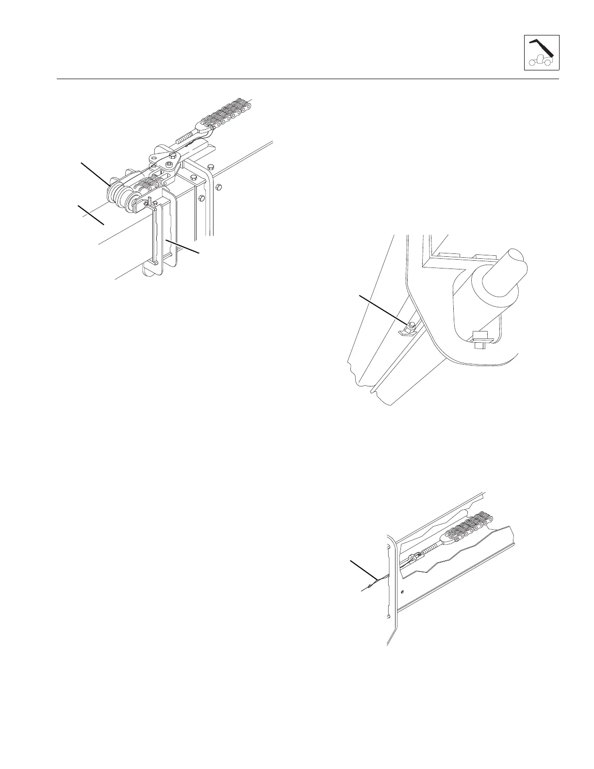
5. At the front underside of the boom, record the amount
of threads extending beyond the locknut (13). This
measurement will be the starting point for adjustment
of the boom retract chain.
6. At the front underside of the boom, loosen the locknut
far enough that it can be removed by hand.
7. Attach a wire or string (14) to the threaded clevis with a
threaded eye or a flat washer tack welded to a
capscrew. The outside diameter of the eye or flat
washer must be smaller than the diameter of the
threads on the clevis. The wire or string will be used to
 Loading...