Cab and Covers
4-5
6036, 6042, 8042, 10042, 10054 31211015
4.3.3 Service Brake Pedal
a. Brake Valve Removal
Refer to Section 8.8.2, “Service Brake Valve”, for removal
information.
b. Brake Valve Installation
Refer to
Section 8.8.2, “Service Brake Valve”
, for installation
information.
c. Service Brake Pedal Removal
1. Park the machine on a firm, level surface, level the
machine, fully retract the boom, lower the boom, place
the transmission in (N) NEUTRAL, engage the parking
brake and turn the engine OFF.
2. Place a Do Not Operate Tag on both the ignition key
switch and steering wheel, stating that the machine
should not be operated.
3. Open the engine rear and side engine doors. Allow the
system fluids to cool.
4. Properly disconnect the battery. Refer Section 9.8,
“Battery”, for procedure.
5. Remove the lower dash panel.
Prior to SN 0160074878, excluding 0160074813
0160074818 and 0160074882
SN 0160074878 to Present, including 0160074813
0160074818 and 0160074882
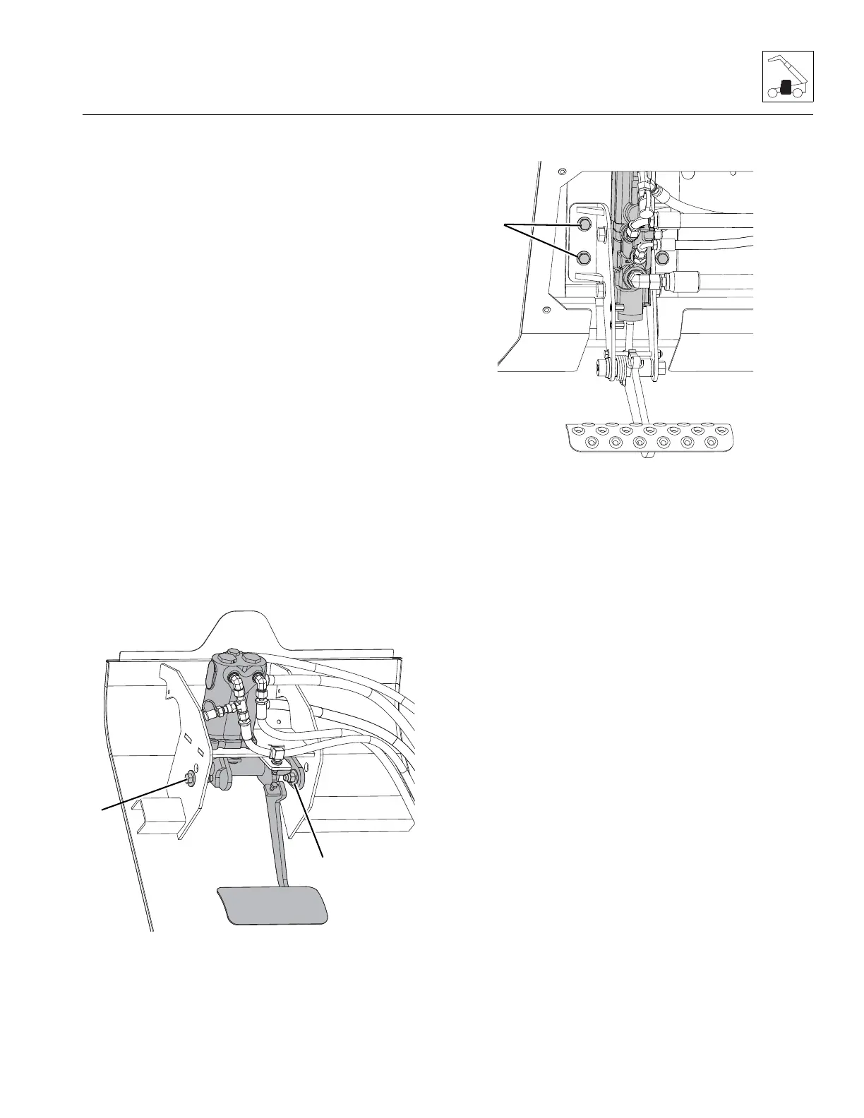
6. Prior to SN 0160074878, excluding 0160074813
0160074818 and 0160074882: Remove the two
capscrews, four flat washers, two pivots and two
nuts (10) securing the service brake pedal to the cab.
7. SN 0160074878 to Present, including 0160074813
0160074818 and 0160074882: Remove four bolts (10)
securing the service brake pedal to the cab.
8. Remove the service brake pedal from the cab.
d. Service Brake Pedal Installation
1. Position the service brake pedal in its mounting location
within the cab.
2. Insert the two brake pedal pivots into mounting
locations on the service brake pedal.
3. Install the service brake pedal with the previously used
hardware.
4. Be sure the brake pedal has the correct range of motion.
Secure pivot pin with bolt and lockwasher.
5. Adjust the service brake switch as needed.
6. Install the lower dash panel.
7. Properly connect the battery. Refer Section 9.8,
“Battery”, for procedure.
8. Remove the Do Not Operate Tags from both the ignition
key switch and the steering wheel.
9. Close and secure the engine rear and side engine doors.