Do you have a question about the Skyware Global 180 and is the answer not in the manual?
| Operating Temperature | -40°C to +60°C |
|---|---|
| Wind Survival | 200 km/h |
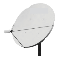
| Antenna Size | 1.8m |
| Frequency Band | C-Band |
| Polarization | Linear (Vertical/Horizontal) |
| VSWR | 1.3:1 |
| Impedance | 50 Ohms |
| Connector Type | N-Type Female |
Instructions for proper disposal of product components, adhering to local regulations.
Guidance on checking contents for damage or missing parts upon receipt.
Specifications for torque values for various bolt sizes and classes.
Visual guide to identify and sort different hardware items used in assembly.
Criteria for choosing an optimal antenna mounting location for signal reception.
List of necessary tools and pre-assembly checks required.
Description and diagrams for pier foundation types for antenna ground poles.
Description and diagrams for deep frost line foundation types.
Technical details and dimensions for the ground pole used with the antenna.
Instructions for assembling the Azimuth/Elevation frame components.
Procedure for attaching the AZ/EL cap to the ground pole.
Steps for mounting the reflector dish to the AZ/EL cap.
Procedure for setting the antenna's elevation angle for optimal signal.
Procedure for setting the antenna's azimuth angle for optimal signal.
Method for making precise adjustments to achieve maximum signal strength.
Instructions for adjusting the feed horn's polarization for correct satellite communication.
Diagram and steps for grounding the main antenna pole.
Instructions for grounding the coaxial cables connected to the feed.
Visual representation of the antenna system with key dimensions.
Technical data on antenna performance under high wind conditions.
Inspection points for the antenna's mounting hardware and structure.
Inspection points for the antenna's main support structure.
Inspection points for the reflector dish and its mounting hardware.
Inspection points for the feed horn's support structure.
Inspection points for the feed horn and RF connection components.
Inspection points for cables, connectors, and grounding.
