11.1 I
2
C Interface
When in I
2
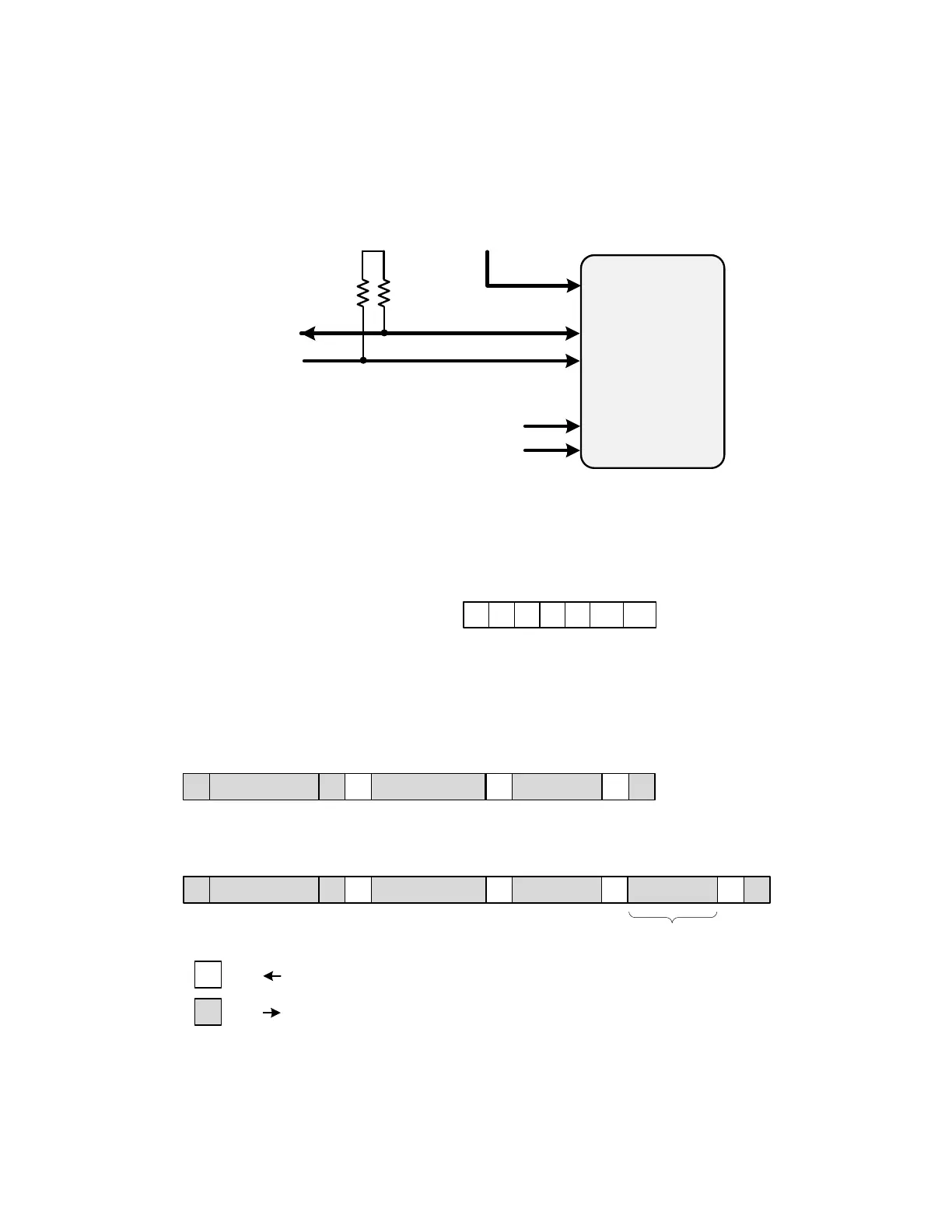
C mode, the serial interface operates in slave mode with 7-bit addressing and can operate in Standard-Mode (100 kbps) or
Fast-Mode (400 kbps) and supports burst data transfer with auto address increments. The I
2
C bus consists of a bidirectional serial data
line (SDA) and a serial clock input (SCL) as shown in the figure below. Both the SDA and SCL pins must be connected to a supply via
an external pull-up (4.7 kΩ) as recommended by the I
2
C specification as shown in the figure below. Two address select bits (A0, A1)
are provided allowing up to four Si5391/Si5391P devices to communicate on the same bus. This also allows four choices in the I
2
C
address for systems that may have other overlapping addresses for other I
2
C devices.
SDA
SCLK
Clock IC
I2C_SEL
VDD
VDDI2C
To I
2
C Bus
or Host
A0
A1
LSBs of I
2
C
Address
I
2
C
Figure 11.2. I
2
C Configuration
The 7-bit slave device address of the Si5391/Si5391P consists of a 5-bit fixed address plus 2 pins which are selectable for the last two
bits, as shown in the following figure.
Slave Address
1 1 1 0 1 A0
0123456
A1
Figure 11.3. 7-bit I
2
C Slave Address Bit-Configuration
Data is transferred MSB first in 8-bit words as specified by the I
2
C specification. A write command consists of a 7-bit device (slave)
address + a write bit, an 8-bit register address, and 8 bits of data as shown in Figure 11.6 SPI Interface Connections on page 46. A
write burst operation is also shown where subsequent data words are written using to an auto-incremented address.
1 – Read
0 – Write
A – Acknowledge (SDA LOW)
N – Not Acknowledge (SDA HIGH)
S – START condition
P – STOP condition
Write Operation – Single Byte
S 0 A Reg Addr [7:0]Slv Addr [6:0] A Data [7:0] PA
Write Operation - Burst (Auto Address Increment)
Reg Addr +1
S 0 A Reg Addr [7:0]Slv Addr [6:0] A Data [7:0] A Data [7:0] PA
Host
Clock IC
Host
Clock IC
Figure 11.4. I
2
C Write Operation
A read operation is performed in two stages. A data write is used to set the register address, then a data read is performed to retrieve
the data from the set address. A read burst operation is also supported. This is shown in the following figure.
Si5391 Reference Manual • Serial Interface
Skyworks Solutions, Inc. • Phone [781] 376-3000 • Fax [781] 376-3100 • sales@skyworksinc.com • www.skyworksinc.com
44 Rev. 0.5 • Skyworks Proprietary Information • Products and Product Information are Subject to Change Without Notice • January 11, 2022 44
 Loading...