15 / 32
Copyright (c) 2009-2013 RoboPeak Team
Copyright (c) 2013-2017 Shanghai Slamtec Co., Ltd.
RPLIDAR encapsulates each measurement sample into a data response packet with
the format showed in the above figure and send the packet out. The descriptions of
every field within the packet are listed in the following table:
Figure 4-5 Field Definition of a RPLIDAR Measurement Result Data Response Packet
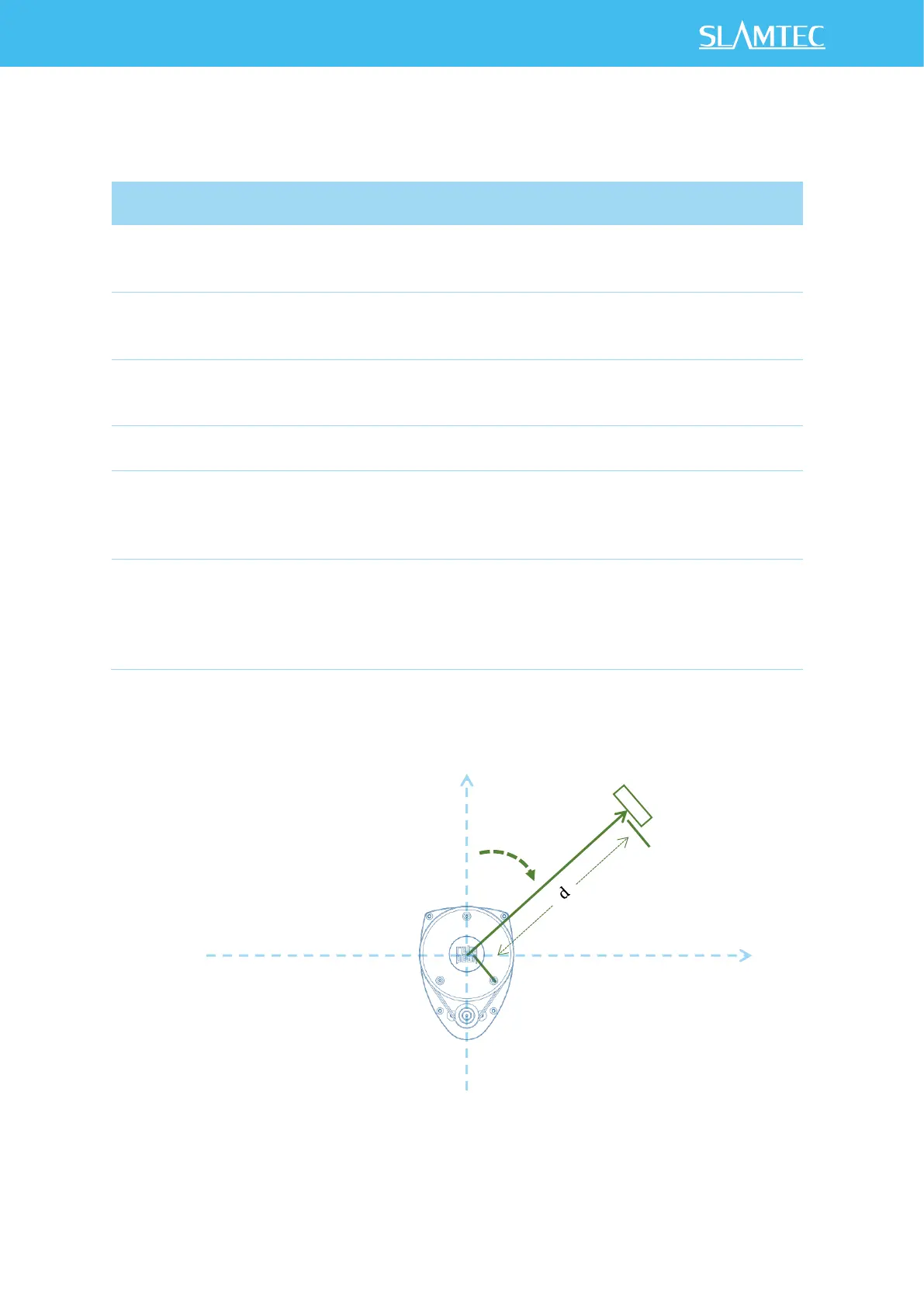
The geometric definition of the included angle and distance value is shown as below:
Figure 4-6 Angle and Distance Value Geometric Definition for RPLIDAR A1 series
Start flag bit of a new scan
When S is set to 1, the current and
incoming packets belong to a new
360
o
scan.
Inversed start flag bit, always has
Can be used as a data check bit.
Check bit, constantly set to 1
Can be used as a data check bit.
Quality of the current measurement
sample
Related the reflected laser pulse
strength.
The measurement heading angle
related to RPLIDAR’s heading. In
degree unit, [0-360)
Stored using fix point number.
Refer to the below figure for
details.
Actual heading =
angle_q6/64.0 Degree
Measured object distance related to
RPLIDAR’s rotation center.
In millimeter (mm) unit.
Represents using fix point. Set to 0
when the measurement is invalid.
Refer to the below figure for
details.
Actual Distance =
distance_q2/4.0 mm
 Loading...