CONTROLS
18
POWER
I
O
RETURN
H.V.
INSULATION RESISTANCE TESTER
RESISTANCE
RESET
SET
DWELL
VOLTAGE
DELAY
2205
EXIT
TEST
CAUTION
HIGH VOLTAGE
MAX.1000VDC
DISCHARGE
G
Ω
M
Ω
H.V.
3
5
1
2 9
10
8
6 74 15
18
17
16
11
14
13
12
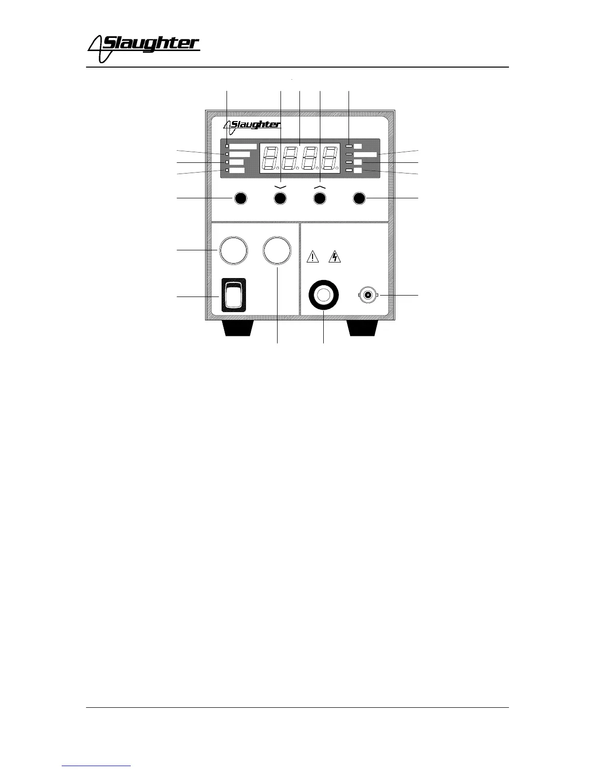
7. UP ARROW (∧): Use this key to increment numeric values in the setup mode.
8. EXIT KEY: Use this key when you desire to exit Setup Mode enter the Run Mode
to initiate a test. This key will also toggle the digital display between Resistance,
Voltage and Dwell during and after tests.
9. HIGH VOLTAGE OUTPUT JACK: For the connection of the detachable 6 foot
(1.82 m) red high voltage test lead. The jack is recessed for safety when this lead is
not being used.
10. RETURN JACK: For the connection of the detachable 6 foot (1.82 m) black,
shielded return test lead.
11. RESISTANCE LED INDICATOR: This indicator illuminates when resistance is
displayed in either test or setup mode.
12. VOLTAGE LED INDICATOR: This indicator illuminates when voltage is
displayed in either test or setup mode.
13. DELAY LED INDICATOR: This indicator illuminates when delay time is
displayed in either test or setup mode.