SETUP
23
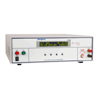
SETUP INSTRUCTIONS FOR Model 2205
Check to be sure the correct input line voltage has been selected on the rear panel (115
volts AC or 230 volts AC). Connect the power input plug into its socket on the rear panel
of the instrument. Connect the male end of the plug to the outlet receptacle.
Please be sure that the safety ground on the power line cord is not defeated and that you
are connected to a grounded power source. Also connect the rear panel chassis ground
for additional safety.
This tester has a safety interlock that must be closed in order for the tester to operate. The
9-pin “D” type plug provided with the unit includes a jumper for the safety interlock. This
plug must be connected for the tester to operate.
Turn on the POWER switch located on the lower left hand side of the front panel. Upon
powering the instrument up a POWER ON SELF TEST (POST) will be automatically
performed. This test will check for the condition of all critical components. In addition
the display will briefly flash the model number and firmware version.
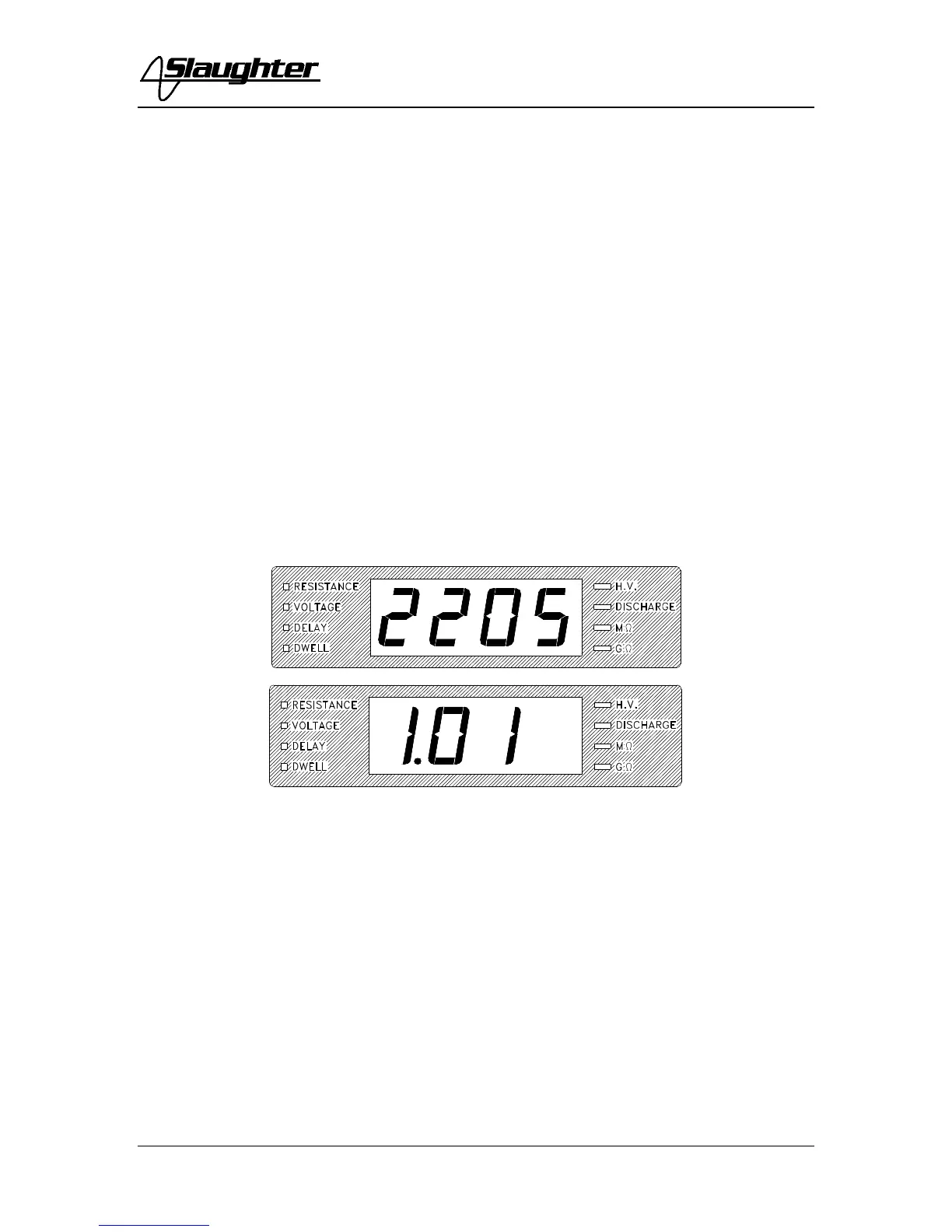
The instrument will recall the last setup that was active. The digital display will show 0.0
and the Resistance LED will be illuminated. To view the last settings, press the set button
once and the Resistance LED will flash and the display will show the programmed
resistance limit. Pressing the Set button again will cause the Voltage LED to flash and the
display will show the programmed voltage. Pressing the Set button a third time will cause
the Delay LED to flash and the display will indicate the delay time. Pressing the Set
button a fourth time will cause the Dwell LED to flash and the display to indicate the
programmed dwell time. Press the Exit button to ready the instrument for testing.
1. To set the Resistance Limit
Press the SET key until the Resistance LED is illuminated and flashing.