Position Designation
D ElectronicSolarSwitch (ESS)
The ESS and the DC connectors together form a DC load-break switch. When
plugged in, the ESS forms a conductive path between the PV array and the in-
verter. Removing the ESS interrupts the DC electric circuit and removing all DC
connectors disconnects the PV array completely from the inverter.
If the inverter is equipped with BLUETOOTH, the BLUETOOTH antenna is inte-
grated in the ESS.
E Protective cover
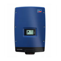
F LEDs
The LEDs indicate the operating state of the inverter (see Section9.1 "LED Sig-
nals", page53).
G Display
The display shows the current operating data and events or errors (see Sec-
tion9.2 "Display Overview", page53).
H Enclosure lid
I Screws and conical spring washers of the enclosure lid
Symbols on the inverter, the ESS and the type label
Symbol Explanation
Inverter
Together with the green LED, this symbol indicates the operating state of
the inverter.
Observe the documentation
Together with the red LED, this symbol indicates an error (for trou-
bleshooting, see the service manual at www.SMA-Solar.com).
BLUETOOTH
Together with the blue LED, this symbol indicates active BLUETOOTH
communication (only in inverters equipped as standard with BLUE-
TOOTH).
Danger
This symbol indicates that the inverter must be additionally grounded if
additional grounding or equipotential bonding is required at the installa-
tion site (see Section6.3.3 "Connecting Additional Grounding",
page31).
4 Product Description
SMA Solar Technology AG
Operating Manual 15STP5-12TL-20-BE-en-15