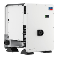
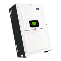
6.2 Overview of the Connection Area
6.2.1 View from Below
Figure 6: Connection areas and enclosure openings at the bottom of the inverter
Position Designation
A Positive DC connectors, input A
B Positive DC connectors, input B
C Pin connector for the ESS
D Pin connector with filler plug for the network connection
E Cable gland M25 with filler plug for the data cables
F Enclosure opening for the AC cable
G Negative DC connectors, input A
H Negative DC connectors, input B
6 Electrical Connection
SMA Solar Technology AG
Operating Manual 27STP5-12TL-20-BE-en-15
 Loading...


