FY301 – Operation, Maintenance and Instructions Manual
1.2
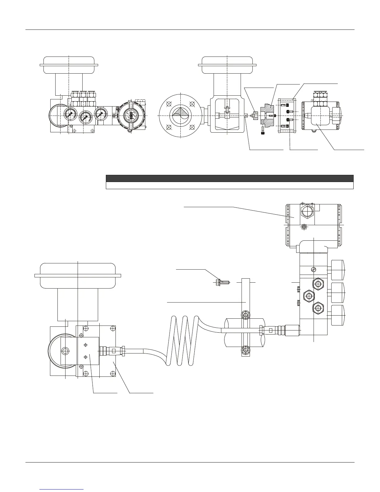
Rotary Movement
Install the magnet on the valve stem using the its proper bracket, according to the Figure 1.1.
LOCK
ROTATY
MAGNET
POSITIONER
VALVE STEM
ROTATY
MAGNETY
BRACKET
POSITIONER
BRACKET
M6x1 SCREWS
Figure 1.1 – Positioner with Rotary Actuator
Included in the package content the centralizer device of rotary magnet. See figure 1.17.
OUT 1
IN
OUT 2
REMOTE
REMOTE EXTENSION
“L” BRACKT WITH “U” CLAMP
FOR REMOTE POSITION
M6x1 SCREWS
(2 PLACES)
Figure 1.2 – Positioner on Rotary Actuator with Remote Position
Then, install the positioner bracket on the actuator. Usually, the actuator is designed according to
the VDI/VDE 3845 standard, and, in this case, tighten the four screws with their lock washers on the
proper bracket.