FY301 – Operation, Maintenance and Instructions Manual
1.4
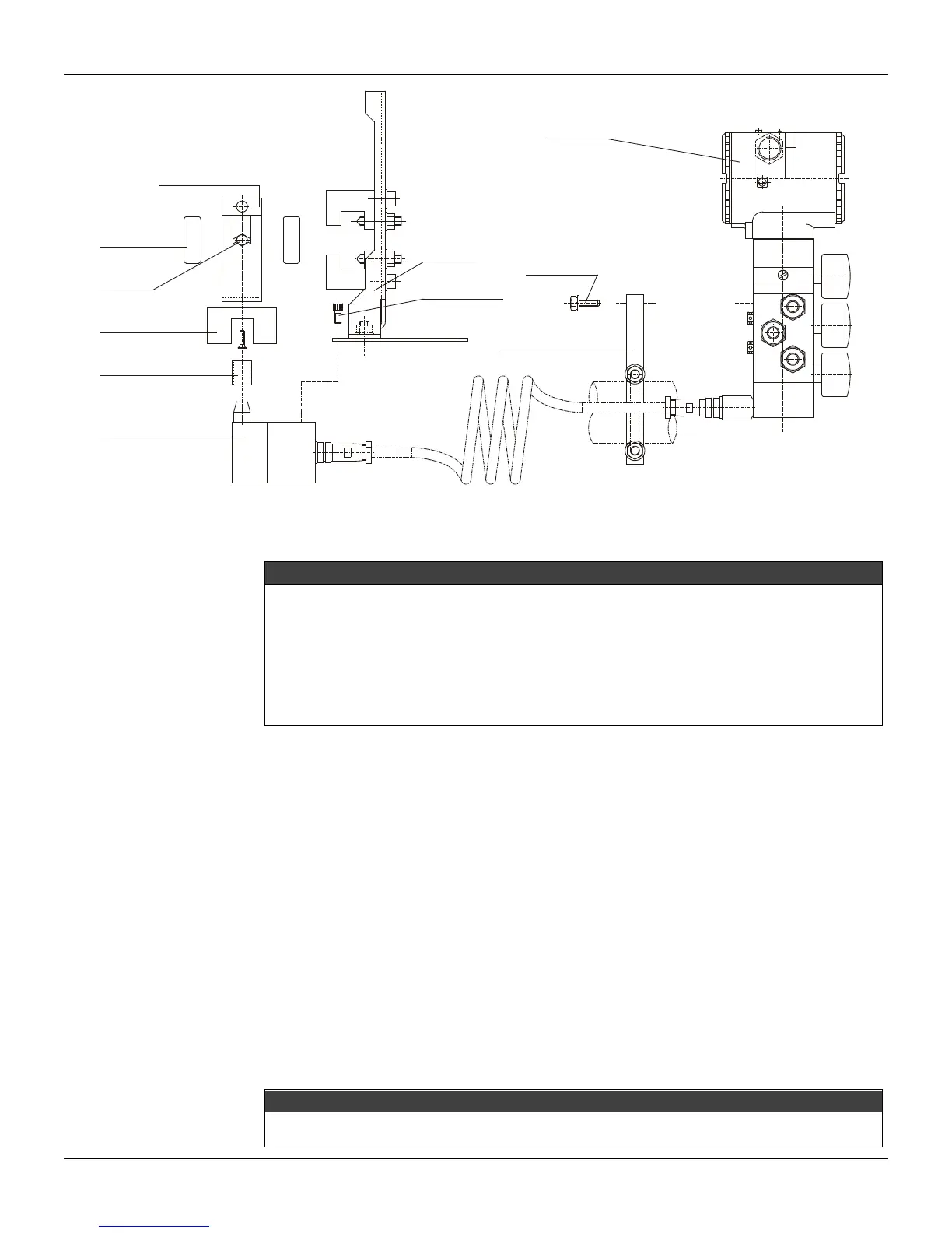
OUT 2
IN
OUT 1
REMOTO EXTENSION
LINEAR MAGENT
VALVE YOKE
VALVE
STEM
CENTRALIZER
DEVICE
REMOTE
POSITION
“L” BRACKT WITH “U” CLAMP
FOR REMOTE POSITION
M6x1 SCREWS
(2 PLACES)
LINEAR MAGNET
BRACKET
POSITIONER
BRACKET
M6x1 SCREWS
(2 PLACES)
Figure 1.4 – Positioner on Linear Actuator with Remote Position
Make sure the bracket does not obstruct the exhaust outputs.
NOTE
Make sure that the arrow engraved on the magnet coincides with the arrow engraved on the positioner when
the valve is in mid travel.
When mounting the magnet, be sure that:
1. There is no attrict between the internal magnet face and the position sensor salience during the
travel (rotary or linear), through the magnet.
2. The magnet and the salience of position sensor must not be distant.
A minimum distance of 2 m m and a m aximum distance of 4mm are recommended between the magnet
external face and t he positioner face. For that, a c entralizer device (linear or rotary) must be us ed. The
centralizer device is in the positioner packing.
Case the positioner installation or magnet change or if any other modification is done, the positioner
will require a re-calibration. See Section 3 (Setup - for Auto Setup procedure).
Pneumatic Connections
The FY301 requires instrument air quality, following the best practices for pneumatic installations.
Consult the American National Standard "Quality Standard for Instrument Air" (ANSI/ISA S7.0.01 -
1996) for detailed information.
The FY301 comes with input and output stainless steel air filters, but these filters do not exclude the
preliminary instrument air treatment. Periodical filter cleaning is recommended at every 6 months or
less, if the air quality is not good. Please, check the maintenance section for clean the filters.
The FY301 supply air pressure varies from 1.4 bar (20 psi) minimum, to 7.0 bar (100 psi) maximum.
The actuator working pressure must follow these limits. Consider the use of boosters, if required.
Pressure below this range shall affect the positioner performance. Pressure above this range may
damage the positioner.
The two pneumatic outputs, marked as “OUT1” and “OUT2”, work in opposite directions to open or
close the valve.
IMPORTANT
If a failure occurs on the FY301, such as power loss (4-20 mA input signal), the output marked OUT1 goes to
zero pressure and the output marked OUT2 goes to the air supply pressure value.