FY301 – Operation, Maintenance and Instructions Manual
5.8
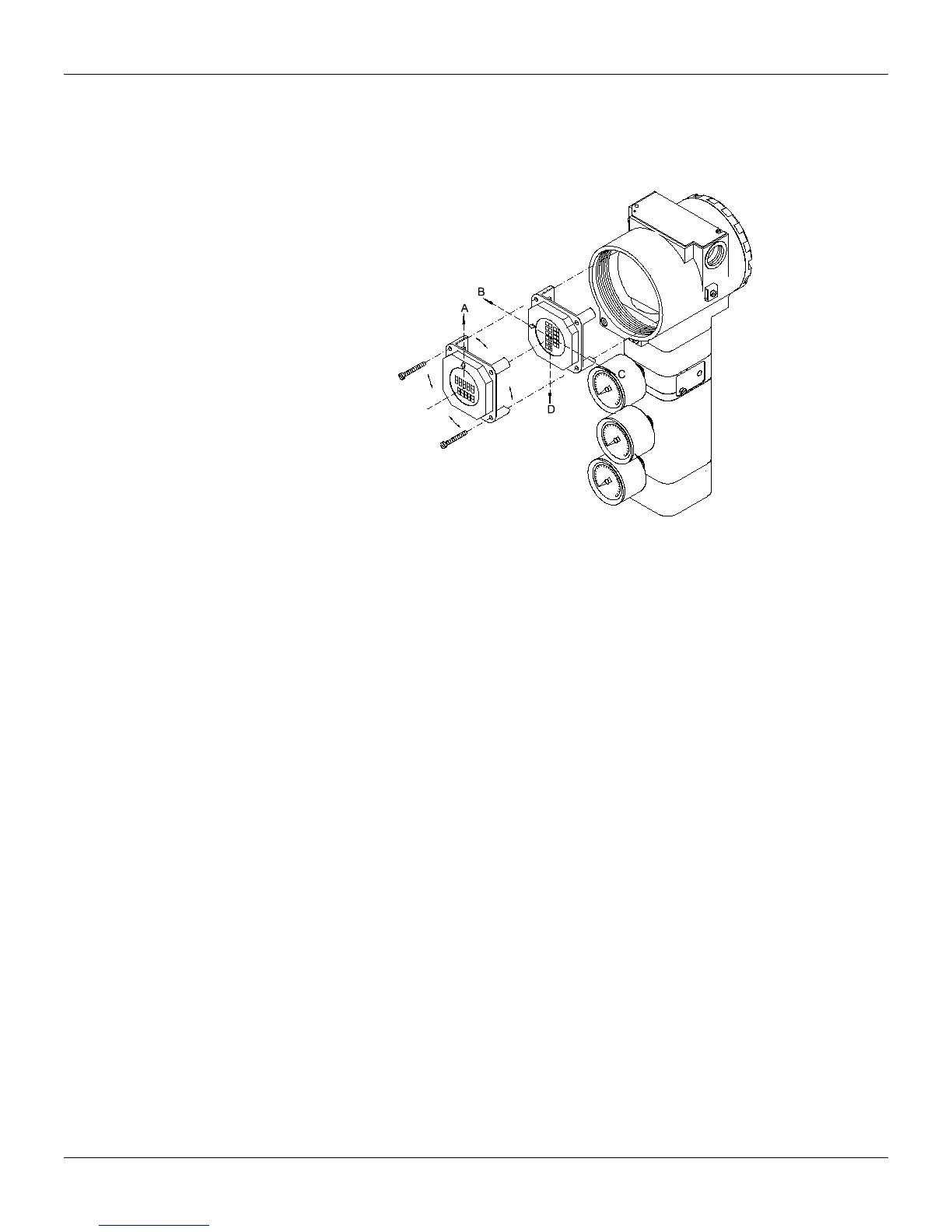
Electronic Circuit
Plug transducer connector and power supply connector to main board (5). Attach the display to the
main board. Observe the four possible mounting positions (Figure 5.2). The mark on the display
indicates up position.
Figure 5.3 – Four Possible Positions for Local Indicator
Anchor the main board and indicator with their screws (3). After tightening the protective cover (1),
mounting procedure is complete. The positioner is ready for powering and testing..
Electrical Connections
The plug must obligatorily be installed in the electric connection not used, preventing the humidity
entrance.
Package Content
When receiving the equipment, verify the package content. The number for items marked with (*) must
be in accordance with the number of positioners delivered.
Positioner
Adequate mounting brackets
- For the positioner
- For the magnet
Magnetic tool for local adjustment (*)
Centralizer transmitter device (*)
Cleaning device for the restriction (*)
Operation, maintenance and instructions manual (*)