FY301 – Operation, Maintenance and Instructions Manual
1.10
CURRENT SUPPLY
OUTPUT
CONFIGURATOR
GROUND THE SIGNAL LOOP AT ONE
END OR LEAVE IT
UNGROUNDED
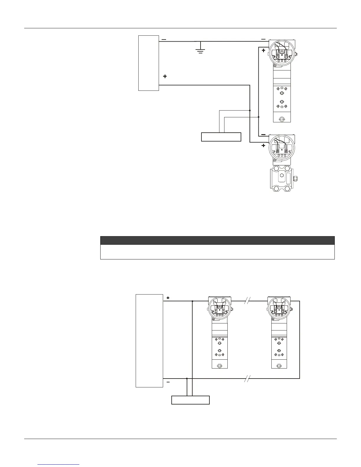
Figure 1.11 - FY301 Wiring Diagram - Connected in the Smar Transmitter
The FY301 has an equivalent impedance of 550 Ohms. Make sure that the current supply or analog
output of DCS, CLP or single loop controller powering the positioner is capable to handle a voltage
drop of 11 V for each positioner (550 x 0.02 = 11 Volts).
NOTE
If you are using two positioners in series as e. g., working in split range, the resulting impedance will be
1.100 Ohms. Therefore, the analog output should be capable to handle a voltage drop of 22 Volts.
Connection of the FY301 in multidrop configuration should be done as in figure 1.12. Note that a
maximum of two positioners can be connected on the same line and that they should be connected
in series.
Figure 1.12 - FY301 Wiring Diagram in Multidrop Configuration (Split Ranges)