Installation Manual STR7202 TAG4 & SFM7704 TAG1
DBCI-0512-0052-V013
STR7202 2-Side Trimmer & SFM7704 Square Fold Module
4. Preparation (continued)
Contents
4.4 Preparing the STR (continued)
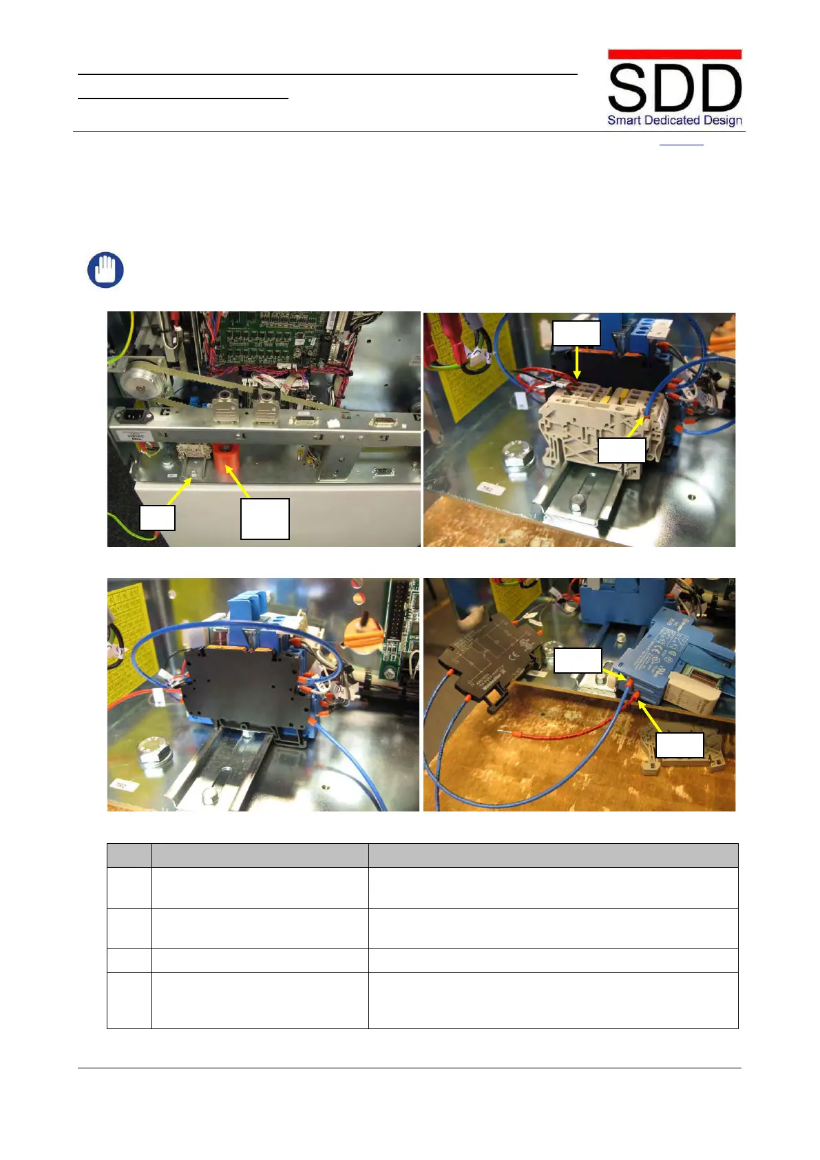
4.4.4 Optocoupler removal (D1 only)
IMPORTANT:
Skip step 4.4.4 for Canon F1 Trimmer.
Fig. 4.4.4.1 Fig. 4.4.4.2
Fig. 4.4.4.3 Fig. 4.4.4.4
Locate Terminal Rail TR2 on right side and remove Safety
Block (Fig. 4.4.4.1).
Disconnect the Red wire from TR2-1 and the Blue wire
from TR2-4 (Fig. 4.4.4.2).
Remove Terminal Clamps and lay aside (Fig. 4.4.4.3).
Loosen Optocoupler and relay K4. Disconnect the Red
Wire from K4-A1 and the Blue Wire from K4-A2 (Fig.