Installation Manual STR7202 TAG4 & SFM7704 TAG1
DBCI-0512-0052-V013
STR7202 2-Side Trimmer & SFM7704 Square Fold Module
5. Installation (continued)
5.2 Electrical Installation
5.2.1 Tapping STR Transformer
Fig.5.2.1.1 Fig.5.2.1.2
Fig.5.2.1.3 Fig.5.2.1.4
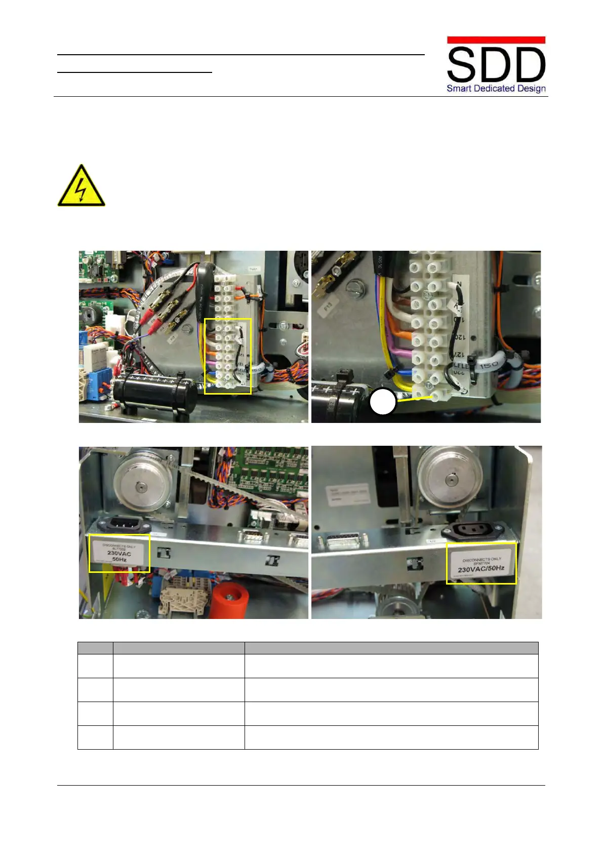
1. Check terminal setting.
Fig.5.2.1.1 shows a transformer tapped for 230V. Check to
which terminal wire [A] KS1-1YL is connected (Fig. 5.2.1.2).
2. Set correct line voltage
If required, connect wire to the appropriate line voltage
3. Disconnect STR-only label
Disconnect label for appropriate line voltage should be placed
on the right front side. Replace if required. (Fig. 5.2.1.3)
4. Disconnect SFM-only label
Attach Disconnect SFM label for appropriate line voltage on
the right rear side. (Fig. 5.2.1.4)
• The STR and SFM should only be connected to an approved electrical system which is rated
at a maximum of 16A and protected by circuit breakers
•
Make sure the STR and SFM power cords are disconnected from a power source.