Installation Manual STR7202 TAG4 & SFM7704 TAG1
DBCI-0512-0052-V013
STR7202 2-Side Trimmer & SFM7704 Square Fold Module
4. Preparation (continued)
Contents
4.4 Preparing the STR (continued)
4.4.4 Optocoupler removal (D1 only) (continued)
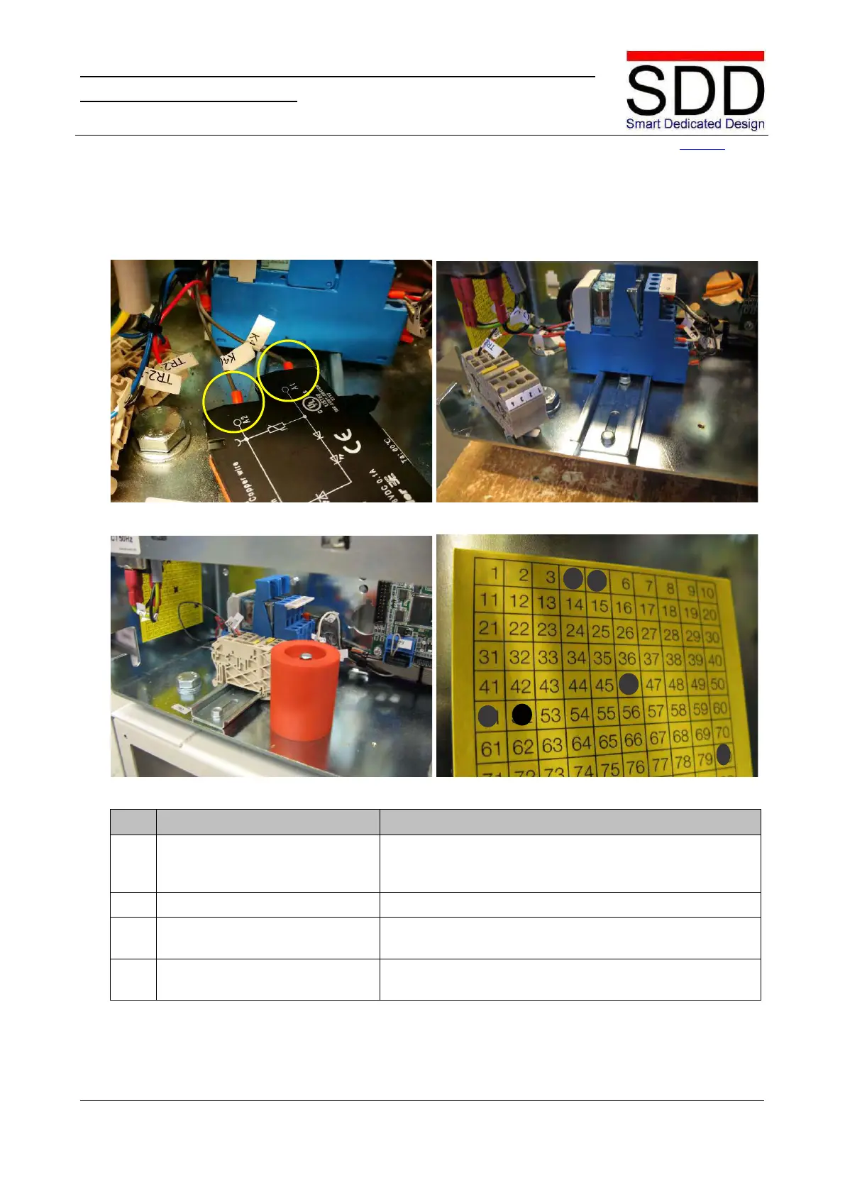
Fig. 4.4.4.5 Fig. 4.4.4.6
Fig. 4.4.4.7
Remove wire K4(2) from OPTO-A2 and mount in K4-A2.
Remove wire K4(1) from OPTO-A1 and mount in K4-A1
Mount relay K4 back into place (Fig. 4.4.4.6).
Place Terminal Clamps and Safety Block back into place
(Fig. 4.4.4.7).
8. Mark TAG label Mark “52” on the TAG label to indicate removal of the