Installation Manual STR7202 TAG4 & SFM7704 TAG1
DBCI-0512-0052-V013
STR7202 2-Side Trimmer & SFM7704 Square Fold Module
5. Installation (continued)
Contents
5.2. Electrical Installation (continued)
5.2.4 Installing Start/Stop Interface in Canon D1 (continued)
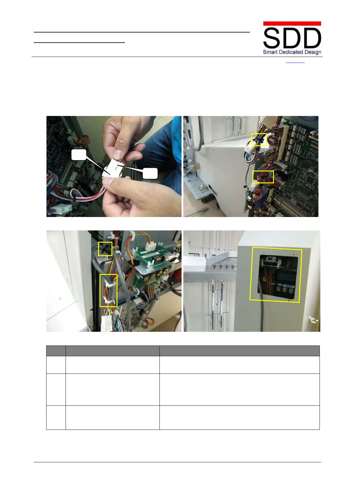
Fig. 5.2.4.13 Fig. 5.2.4.14
Fig. 5.2.4.15 Fig. 5.2.4.16
Install Start/Stop Interface
Cable, part 3.
Connect [J5] to [P5] on the Communication Cable (Fig.
5.2.4.13).
Secure Start/Stop Interface &
Communication Cables.
• Bundle and Secure multi-core cable with Tie Wraps
as marked in Fig. 5.2.4.14.
• Attach Communication Cable in clamps and fasten
with Tie Wrap as marked in Fig. 5.2.4.15.
Lead out Communication cable via aperture in Rear
Cover (Fig. 5.2.4.16) and mount cover back in place by