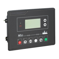
HGM6110/6120 AUTO START MODULE
HGM6110/6120 Auto Start Module ISSUE 2.0 2008-10-27 Page 12 of 24
6. CONNECTING TERMINAL
Pin Function Dim Description
1
DC Plant Supply Input
(-ve)
2. 5mm
System DC negative input.
(Battery Negative).
2
DC Plant Supply Input
(+ve)
2. 5mm
System DC positive input.
(Battery Positive).(Recommended
Maximum Fuse 20A)
3 Emergency Stop Input 2. 5mm
Plant Supply +ve. Also supplies fuel &
start outputs.
(Recommended Maximum Fuse 32A)
4 Fuel relay Output 2. 5mm
Plant Supply +ve from pin 3.
7 Amp rated.
5 Start relay Output 2. 5mm
Plant Supply +ve from pin 3.
7 Amp rated.
6 Auxiliary Output relay 1 1.5mm
Plant Supply +ve from
pin 2.
7 Amp rated.
7
8
9
Auxiliary Output relay 2 1.5mm
Free voltage contacts.
7 Amp rated
10
11
Auxiliary Output relay 3 2.5mm
12
13
Auxiliary Output relay 4 2.5mm
Free voltage contacts.
16 Amp rated
Reference
table 2
14 Charge fail / excite 1.0mm
Do not connect to ground (battery –ve)
15 Magnetic pickup +ve
16 Magnetic pickup -ve
Connect to Magnetic Pickup device
 Loading...