Specifi cations
Example of Operation Command
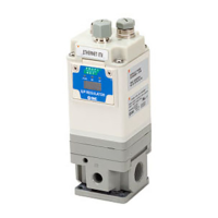
Model
JXC91
Compatible motor Step motor (Servo/24 V DC)
Power supply Power voltage: 24 V DC±10 %
Current consumption 130 mA or less (Controller)
Compatible encoder Incremental A/B phase (800 pulse/rotation)
Communication
Protocol EtherNet/IP™
Communication speed 10/100 Mbps (Auto negotiation)
Communication method Full duplex/Half duplex (Auto negotiation)
Confi guration fi le
Note)
EDS fi le
I/O occupation area Input 36 bytes/Output 36 bytes
IP address setting range
Rotary switch settings: 192.168.1.1 to 254
Through DHCP server: Optional address
Device information
Vendor ID: 7h (SMC Corporation)
Product type: 2Bh (Generic Device) Product code: D1h
Memory EEPROM
LED indicator PWR, ALM, MS, NS
Cable length [m] Actuator cable: 20 or less
Cooling system Natural air cooling
Operating temperature range [°C] 0 to 40 (No freezing)
Operating humidity range [%RH] 90 or less (No condensation)
Insulation resistance [MΩ]
Between all of external terminals and the case
50 (500 V DC)
Weight [g] 210 (Screw mounting), 230 (DIN rail mounting)
In addition to the step data input of 64 points maximum in EtherNet/IP™ communication, the changing of each parameter can be performed in
real time in the numerical data defi ning operation.
<Application Example> Movement between 2 points
No.
Movement mode
Speed Position
Acceleration Deceleration
Pushing force
Trigger LV
Pushing speed
Moving force
Area 1 Area 2 In position
0
1: Absolute
100 10 3000 3000 0 0 0 100 0 0 0.50
1
1: Absolute
100 100 3000 3000 0 0 0 100 0 0 0.50
<Step No. defi ning operation>
Sequence 1: Servo ON instruction
Sequence 2: Instruction to return to origin
Sequence 3: Specify step data No. 0 to input the DRIVE signal.
Sequence 4: Specify step data No. 1 after the DRIVE signal is turned OFF to input the DRIVE signal.
<Numerical data defi ning operation>
Sequence 1: Servo ON instruction
Sequence 2: Instruction to return to origin
Sequence 3:
Specify step data No. 0 and turn ON the input instructions fl ag (position) and input 10 in the target position. Subsequently the start fl ag turns ON.
Sequence 4: Turn ON step data No. 0 and the input instructions fl ag (position) to change the target position to 100 while the start fl ag is ON.
The same operation can be performed with any operation command.
0 10 100
Sequence 1
Sequence 2
Sequence 3
Sequence 4
Note) The fi le can be downloaded from the SMC website.
왎Trademark
EtherNet/IP™ is a trademark of ODVA.
3
Series JXC91

 Loading...