HRX-OM-W004
Chapter 1 Read before using
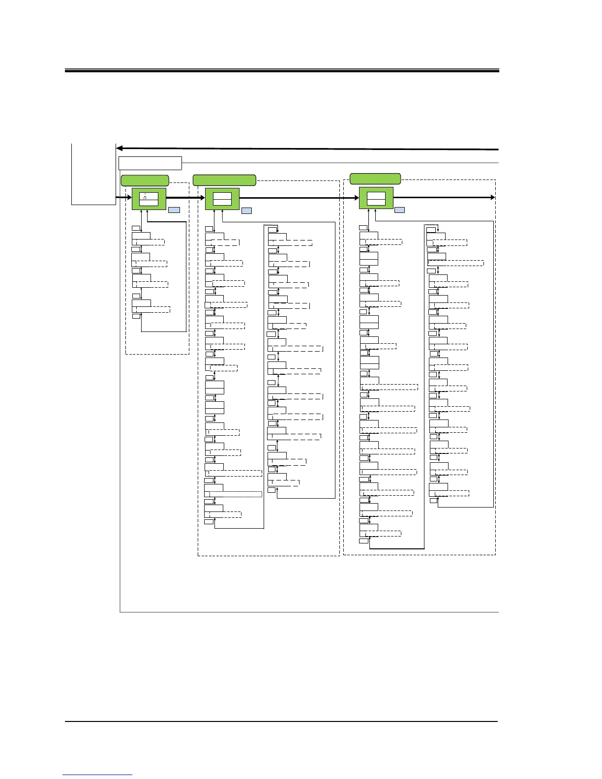
1.3
Key operations
HRR Series
1-6
Fig 1.3-3 Key operation (3/4)
EASY mode
resetKey click sound
Electric conductivity
set valve hysteresis*1
Unuse
d
ON
ON
WAKE
250
DISP
50
DIHYS
OFF
EXTMD
PUMPF
00
▲/▼
▲/▼
▲/▼
▲/▼
▲/▼
Key-lock
OFF
▲/▼
Circulating fluid temp time
outside monitoring range
5
WRM
▲/▼
SET
MENU
MENU
KEY ⇒ LOCK
EASY ⇒ MODE
KEY ⇒ CLICK
Offset mode
OFF
▲/▼
OFSET ⇒ MODE
00
▲/▼
OFSET ⇒ TEMP
▲/▼
EXT ⇔ OFSET
TEMP ⇒ OUT ⇒ OVER
DI filter maintenance
time*1
Dustproof filter
maintenance time
*Air-coold type only
5000
FILTT
5000
FUNUP
▲/▼
▲/▼
▲/▼
DI ⇔ TIME
050
5
WRN
HIPRS
HIPRS
HITEM
40
LOFL
5
LOTEM
450
DIHI
ON
ON
OFF
400
Detection time of circulating
fluid discharge pressure
rise alarm
Changing of the flow
rate decrease alarm
Setting of low flow
rate alarm
Detection time of low
flow rate alarm
Setting of electric
conductivity increase
alarm*1
Switching circulating fluid
temperature drop alarm
Switching circulating fluid
temperature drop alarm
Unused
Unused
Setting of circulating fluid
discharge pressure
rise alarm
▲/▼
▲/▼
▲/▼
▲/▼
▲/▼
▲/▼
▲/▼
▲/▼
▲/▼
▲/▼
FLT
Changing of circulating fluid
discharge pressure
rise alarm
▲/▼
ALST
MENU
▲/▼
MENU
HIPRS ⇒ ALARM
TEMP ⇒ OUTHI ⇒ OUTP
TEMP ⇒ OUTLO ⇒OUTP
AMB ⇒ TEMP ⇒ ALARM
AMB ⇒ HITEMP
Alarm setting menu
FLTR ⇔ TIME
Lower limit of circulating
fluid temperature
monitoring function
Circulating fluid temp
monitoring start time
PUMPP
600
WRM
50
▲/▼
▲/▼
TEMP ⇒ OUT ⇒ TYPE
TEMP ⇒ OUT ⇒ START
HIPRS ⇒ TIME
LOFL ⇒ ALARM
LOFL ⇒ TIME
OFF
Switching circulating fluid
temperature range rising
alarm
▲/▼
TEMP ⇒ OUTLO ⇒ ALARM
Alarm buzzer sound
ON
ALARM ⇒ BUZZ
▲/▼
Unused
Pressure of lower
pressure refrigerant
circuit
Pressure of higher
pressu rerefrigerant
circuit
000
000
▲/▼
▲/▼
ON
MENU
MENU
REF ⇔ PRSHI
REF ⇔ PRSLO
212
▲/▼
REF ⇔ TEMP
Ambient temperature
*Air-cooled type only
212
AMB ⇔ TEMP
▲/▼
▲/▼
Advance setting mode
0
0
WRN
Contact input signal 2
Delay timer
Contact input signal 2
OFF Detection timer
▲/▼
▲/▼
▲/▼
INP2 ⇒ DELAY
INP2 ⇒ OVER
COMM ⇒ ALARM
Changing of
communication error
monitoring alaarm
OFF
▲/▼
MANT ⇒ ALARM
Changing of
maintenance alarm
Monitor menu
Standard setting menu
Offset temperature
Electric conductivity set
valve* 1
PUMPF
350
▲/▼
Unuse
d
FLT
Changing of contact
input signal 2 detection
alarm
INP2 ⇒ ALARM
▲/▼
Switching circulating fluid
temperature range rising
alarm
OFF
PUMPF
▲/▼
TEMP ⇒ OUTHI ⇒ ALARM
0
0
INP2
INP2
Contact input signal
1Delay timer of reading
Contact input signal 1
OFF Detection timer
▲/▼
▲/▼
INP1 ⇒ DELAY
FLT
Changing of contact
input signal 1 signal
detection
INP1 ⇒ ALARM
▲/▼
EXT ⇔ CTRL
EXT ⇒ HITMP ⇒ LIMIT
Upper limit of circulating
fluid temperature
monitoring function
400
▲/▼
TEMP ⇒ OUT ⇒ HITMP
Unused
10
WAKE
Unuse
d
100
▲/▼
EXT ⇒ LOTMP ⇒ LIMIT
EXT ⇔ TIME
▲/▼
Temperature of the
compressor inlet
Basic
setting
mode
10
READY ⇒ HBEND
TEMP READYband
width Upper Limit
▲/▼
-10
▲/▼
READY ⇒ LBRND
TEMP READY Band
width Lower Limit
180
▲/▼
READY ⇒ TIME
TTEMP READY
stabilization time
600
▲/▼
READY ⇒ START
TTEMP READY alarm
monitoring start time
5
▲/▼
TEMP ⇒ OVER
TTEMP READY
Time when it goes away
▲/▼
▲/▼
TEMP READY alarm
OFF
PUMPF
TEMP ⇒ READY ⇒ ALARM
TEMP READY alarm output
added
ON
PUMPF
TEMP ⇒ READY ⇒ OUTP
▲/▼
100
Unused
▲/▼
AMB ⇒ LOTEMP
ARN
Switch leakage alarm
WATER ⇒ LEAK ⇒ ALARM
▲/▼
▲/▼
INP1 ⇒ OVER
30
▲/▼
COMM ⇒ TIME
The monitoring time of
communication error
0
PUMP ⇒ TIME
Time when only pump
rus when alarm is generated
▲/▼
400
PUMP ⇒ TEMP
Temp when only pump
rus when alarm is generated
▲/▼
CTRL
dDI
▲/▼
Electric conductivity
control methhod* 1
DI ⇒ CTRL
Circulating fluid temperature
range increases, the monitoring
method of lowering alarm
RNST
WRM
TEMP ⇒ OUT ⇒ ALARM
▲/▼

 Loading...