HEC-OM-S002
Chapter 5 Operation
5.1 Operation of Controller
5-1
Chapter 5 Operation
5.1 Operation of Controller
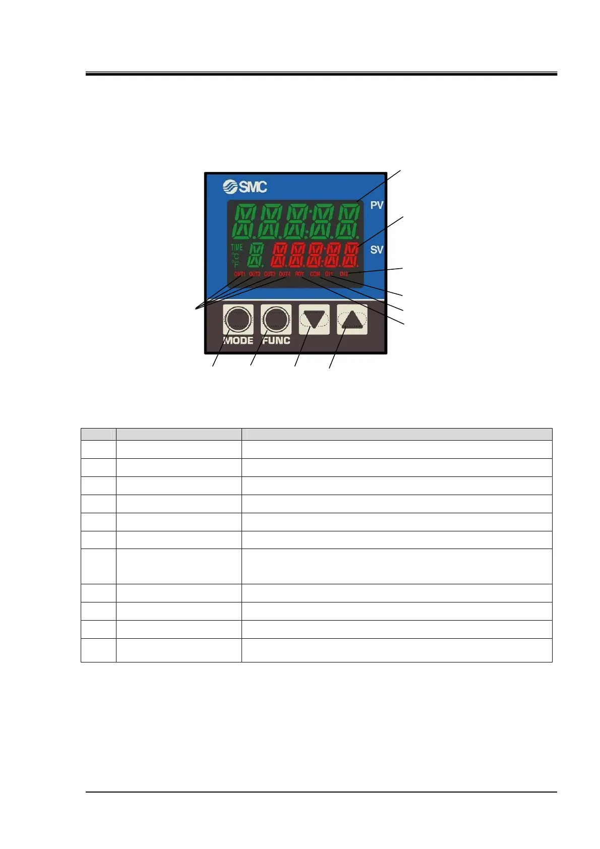
5.1.1 Details of Controller
Fig. 5-1 Details of operation and display panel
Table 5-1 Details of operation and display panel
No. Description Detail
①
LCD1 Displays characters indicating temp. control or setting content.
②
LCD2 Displays set temperature or each selected input value.
③
[▼] key (DOWN key)
Decreases set data.
④
[▲] key (UP key)
Increases set data.
⑤
[MODE] key Used to change screens and modes.
⑥
[FUNC] key Used to shift digits of SV
⑦
Output LED
OUT1: Lights up during heating.
OUT2: Lights up during cooling.
OUT4: Lights up when DI 1 or DI2 LED is lighted up.
⑧
DI1 LED Lights up Level switch alarm occurs.
⑨
DI2 LED Lights up thermostat alarm occurs.
⑩
Communication LED Flashes during communication. Normally, it remains on.
⑪
RDY LED
Lights up when control is stopped.
Refer to page 5-9, “5.1.9 Details of Control Setting Mode”.
①
②
③
④
⑤
⑥
⑦
⑪
⑩
⑧
⑨
 Loading...