-15-
No.LFE****-OMZ0012
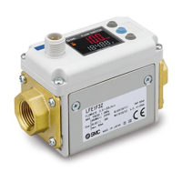
Mounting and Installation
Installation
- Be sure to use the product within the specified operating pressure and temperature range.
- Proof pressure is 2MPa.
Proof pressure depends on fluid temperature. Refer to the chart of the operating pressure range (page 28).
Mounting
- Never mount the switch in a place that will be used as a scaffold.
- Mount the product so that the fluid flows in the direction indicated by the arrow on the side of the body.
- Check the flow characteristics data for pressure loss (page 26) and the straight inlet pipe length effect on
accuracy (page 27), to determine inlet piping requirements.
- Do not suddenly reduce the piping diameter.
- In the non-isolated type, the piping port is connected to the negative terminal of the power supply, and this
product is usable in the negative ground system only.
The positive ground system is not accepted.
- In the isolated type, the piping port is isolated from the power supply, and this product is usable in wiring
connections from the negative and positive ground systems.
Ground connection and wiring method for the non-isolated type (LFE□)
Ground connection and wiring method for the isolated type (LFE□Z)
 Loading...