EasyManua.ls Logo

SMC Networks PF3A801H-L

Default Icon
104 pages
To Next Page IconTo Next Page
Loading...
No.PF※※-OMY0005
PRODUCT NAME
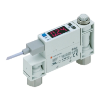
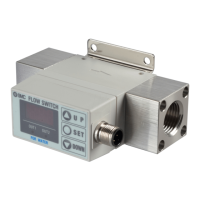
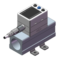
Digital Flow Switch
(Modular type)
MODEL/ Series/ Product Number
PF3A801H-L
PF3A802H-L

Questions and Answers:

SMC Networks PF3A801H-L Specifications

General IconGeneral
Number of Ports8
Power over Ethernet (PoE)No
Switching Capacity16 Gbps
Forwarding Rate11.9 Mpps
Weight0.7 kg
MAC Address Table8K entries
Throughput11.9Mpps
Port TypeGigabit Ethernet
Dimensions28 mm x 220 mm x 130 mm
MAC Address Table Size8K entries
Status IndicatorsLink/Activity
Ports8 x 10/100/1000Base-T

Summary

Safety Instructions

Hazard Level Definitions

Defines hazard levels (Caution, Warning, Danger) used in safety instructions.

General Safety Precautions

Outlines essential safety measures and precautions for product operation and handling.

Product Use and Warranty Disclaimer

Details product usage guidelines, warranty terms, and compliance requirements.

Operational Safety Warnings

Lists critical warnings regarding disassembly, operation outside specifications, and hazardous environments.

Handling and Usage Precautions

Provides precautions for handling the product, including electrical safety and environmental considerations.

Product Handling and Mounting

General Handling Precautions

Essential guidelines for safely handling the product, including avoiding shock and damage.

Mounting Guidelines

Specifies correct mounting procedures, including torque, orientation, and avoiding vibration.

Wiring Best Practices

Environmental Considerations

Adjustment and Operation

Operational Steps and Settings

Guides users through initial setup, operation sequence, and parameter adjustments.

Routine Maintenance Procedures

Model Indication and Ordering

Product Model Configuration

Explains the structure of the product model number for correct identification.

Accessories and Part Numbers

Lists available accessories and their corresponding part numbers for ordering.

Product Components and Identification

Body and Connector Pinout

Identifies the main body components and details the connector pin assignments.

Component Descriptions

Provides descriptions of individual components like display, connector, and piping ports.

Display Unit and Controls

Display Elements and Functions

Describes the main display, sub display, operation LED, and control buttons.

IO-Link Status Indicator

Explains the function and meaning of the IO-Link status indicator light.

IO-Link Communication Status

Indicator Light and Screen Display

Details the meaning of IO-Link status indicator lights and screen messages during communication.

Technical Definitions and Terminology

Glossary A-E

Defines technical terms from Accumulated flow to Error display.

Glossary F-N

Defines technical terms from F.S. to Normal condition.

Glossary O-R

Defines technical terms from Operating mode to Repeatability.

Glossary S-Z

Defines technical terms from Set point range to Zero-clear function.

Mounting and Installation

Mounting Orientation and Display Rotation

Guides on correct mounting orientation and how to rotate the display for optimal visibility.

Flow Direction

Indicates the direction of fluid flow on the product body.

Piping and Connections

Piping Installation and Tightening Torque

Details the procedure for installing piping and the required tightening torque for screws.

Modular Combinations and Options

Lists available options for connecting modular units and adapters.

Moment Load Considerations

Warns about moment loads on piping and suggests support measures to prevent damage.

Electrical Wiring

Connection and Disconnection Procedures

Provides step-by-step instructions for connecting and disconnecting electrical wires and connectors.

Connector Pinouts for Output and IO-Link

Specifies pin assignments for switch outputs and IO-Link communication.

Internal Circuit Diagrams

Illustrates the internal circuitry for NPN and PNP output types.

Wiring Examples for Pulse Output and IO-Link

Provides practical wiring examples for accumulated pulse output and IO-Link device configuration.

Operation Modes and Settings Navigation

Measurement Mode Overview

Describes the primary mode for measurement, display, and switch function operation.

Accessing Setting Modes

Details how to navigate to different setting modes for configuration.

Setting Adjustment: 3-Step Mode

3-Step Setting Mode Description

Explains the 3-step mode for adjusting set values and hysteresis simply.

Default Set Values

Provides the factory default settings for set values and hysteresis for different models.

Hysteresis Mode Operation

Guides on operating the hysteresis mode to set values and hysteresis using buttons.

Window Comparator and Accumulated Output Modes

Describes settings for window comparator and accumulated output modes within the 3-step setting.

Setting Adjustment: Simple Mode

Simple Setting Mode Operation

Details how to adjust set value, hysteresis, and delay time using the simple setting mode.

Simple Mode for ComparatorAccumulated

Describes using the simple mode for window comparator and accumulated output configurations.

Function Settings Configuration

Function Selection Mode Overview

Introduces the function selection mode for configuring individual parameters (F0-F99).

Default Settings Reference

Function Default Values

Provides a table of default settings for all configurable functions (F0 to F99).

Function F0: System and Output Configuration

Reference Condition Settings

Defines standard and normal conditions for measurement reference.

Units, Switch Type, Output Object, Display Color

Details settings for units, switch output type, output object selection, and display color.

Setting Reference Condition and Units

Guides on setting the reference condition and selecting display units.

Setting Switch Output and Output Object

Covers selection of switch output type (NPN/PNP) and output object (OUT1/OUT2).

Selecting Display Color

Describes how to select the display color for the main screen.

Function F1: OUT1 Output Settings

Switch Output Modes for OUT1

Explains various switch output modes like Hysteresis, Window Comparator, Accumulated, Error, and OFF.

Selecting Target for OUT1 Settings

Details how to select the target parameter (Flow, Temp, Pressure, etc.) for OUT1 settings.

Setting Flow, Temp, Pressure Modes

Guides on setting output mode, reversed output, set value, and hysteresis for flow, temp, pressure.

Setting Delay Times for OUT1

Details how to configure ON and OFF delay times for the OUT1 signal.

Setting Accumulated Flow for OUT1

Covers settings for reversed output and accumulated increment/decrement for accumulated flow.

Setting Accumulated Pulse Output for OUT1

Guides on setting reversed output and accumulated pulse value for OUT1.

Setting Error Output for OUT1

Explains how to configure reversed output for error output mode.

Setting Output OFF for OUT1

Details how to set the output to OFF mode for OUT1.

Function F2: OUT2 Output Settings

Configuring OUT2 Output Mode

Explains how to configure the output mode for OUT2, referencing OUT1 settings.

Function F3: Digital Filter Settings

Digital Filter for Flow Rate

Details how to set the digital filter to reduce noise in flow rate measurements.

Digital Filter for Pressure

Details how to set the digital filter to reduce noise in pressure measurements.

Function F6: Display Value Adjustment

Fine Adjustment of Pressure Display

Allows manual fine-tuning of the displayed pressure value within a specific range.

Function F13: Reverse Display Setting

EnablingDisabling Reverse Display

Enables rotating the display and reversing button functions for installation flexibility.

Function F14: Zero Cut-Off Setting

Zero Cut-Off for Flow Rate

Sets the display to zero for low flow rate values to improve accuracy.

Zero Cut-Off for Pressure

Sets the display to zero for low pressure values to improve accuracy.

Flow Rate Zero Cut-Off Ranges

Table showing displayable flow rate ranges based on zero cut-off settings.

Pressure Zero Cut-Off Ranges

Table showing displayable pressure ranges based on zero cut-off settings.

Impact of Zero Cut-Off on Set Points

Describes how zero cut-off settings affect operating points and hysteresis.

Function F16: Measurement Display Settings

Configuring Displayed Measurements

Allows users to choose which measurements (Pressure, Temp, Accumulated Flow) are displayed.

Function F30: Accumulated Value Hold

Enabling Accumulated Value Storage

Enables storing the accumulated flow value in memory periodically to prevent data loss.

Function F80: Display OFF Mode

Automatic Display Turn-Off

Configures the display to automatically turn off after a period of inactivity to save power.

Function F81: Security Code Settings

Enabling and Disabling Security Code

Allows enabling or disabling the security code to prevent unauthorized access.

Changing the Security Code

Provides steps for changing the security code when the device is unlocked.

Function F90: All Functions Setting

EnablingDisabling All Functions

Allows enabling or disabling all configurable functions simultaneously.

Function Setting Order Reference

Provides a reference table for the order in which functions can be set.

Function F96: Cycle Time Check

Checking IO-Link Cycle Time

Enables checking the average cycle time for IO-Link communication.

Function F98: Output Check

Selecting Output Check Mode

Allows selecting between normal output and forced output checks for verification.

Checking Accumulated Pulse Output

Guides on checking accumulated pulse output for OUT1 and OUT2.

Checking Accumulated SW1 Bit

Details checking the accumulated SW1 bit status for IO-Link communication.

Checking Accumulated SW2 Bit

Details checking the accumulated SW2 bit status for IO-Link communication.

Checking Flow Rate SW1 SW2 Bits

Details checking the flow rate SW1 and SW2 bit status for IO-Link.

Checking Temperature SW1 SW2 Bits

Details checking the temperature SW1 and SW2 bit status for IO-Link.

Checking Pressure SW1 Bit

Details checking the pressure SW1 bit status for IO-Link.

Checking Pressure SW2 Bit

Details checking the pressure SW2 bit status for IO-Link.

Checking Flow Rate Unit and Criteria Bits

Details checking the flow rate unit and criteria bit status for IO-Link.

Checking Flow Rate Diagnosis Bit

Details checking the flow rate diagnosis bit status for IO-Link.

Checking Temperature Diagnosis Bit

Details checking the temperature diagnosis bit status for IO-Link.

Checking Pressure Diagnosis Bit

Details checking the pressure diagnosis bit status for IO-Link.

Checking Error and System Error Bits

Details checking error and system error bit status for IO-Link.

Checking Accumulated Value

Details checking the accumulated value status for IO-Link.

Checking Flow Rate, Temperature, and Pressure

Guides on checking flow rate, temperature, and pressure values for IO-Link.

Function F99: Reset to Default Settings

Restoring Factory Default Values

Guides on how to reset all product settings to their original factory defaults.

Other Settings and Functions

Reset Operations

Describes how to reset accumulated flow, peak, and bottom values.

Snap Shot Function

Allows capturing and storing the current measured value as a set point.

Display Select Function

Allows temporary switching of accumulated flow display digits for better readability.

Zero-Clear Function

Allows adjusting the pressure display to zero within a specified range.

Key-Lock Function Operation

Details how to lock and unlock the device keys to prevent accidental changes.

Maintenance and Recovery

Product Reset After Power Loss

Guides on resetting the product after unexpected power interruptions or de-energization.

Security Code Recovery Procedure

Provides steps for recovering the security code if it has been forgotten.

IO-Link Specifications

Outline of IO-Link Functions

Describes communication, status monitoring, and data storage capabilities via IO-Link.

Communication Specifications

Lists key communication parameters for IO-Link, including version and speed.

Process Data Structure

Process Data Bit Offset Mapping

Details the bit offset mapping for various process data items exchanged with the master.

Endian Data Format

Explains the Big-Endian and Little-Endian data formats for transmission methods.

Measurement and Setting Ranges

Flow, Temperature, Pressure Ranges

Specifies the rated and settable ranges for flow, temperature, and pressure measurements.

PD Value Ranges

Lists the ranges for Process Data (PD) values corresponding to measurements.

Process Data Conversion Formulas

Provides formulas for converting between process data and measured values.

IO-Link Parameter Configuration

IODD File Information

Describes the IODD file and its purpose for establishing IO-Link communication.

Service Data: Direct Parameters

Lists direct parameters like Vendor ID and Device ID accessible via IO-Link.

ISDU Parameters Overview

Provides an overview of ISDU parameters, including system commands and device lock.

System Commands and Device Lock

Details system commands for device control and the device access lock function.

Device State Definitions

Describes the meanings of different device states like Normal Operation, Failure, etc.

Detailed Device Status Events

Lists detailed event contents, classifications, and error codes for device status monitoring.

Product Individual Parameters

OUT1 Parameter Settings

Details configurable parameters for OUT1, including flow, temperature, and pressure settings.

OUT2 Parameter Settings

Details configurable parameters for OUT2, including flow, temperature, and pressure settings.

OUT1 OUT2 Accumulated and Pulse Settings

Details settings for accumulated flow, pulse output, and related parameters for OUT1/OUT2.

OUT1 OUT2 Delay Time and Error Settings

Details settings for delay times, and error/off modes for OUT1/OUT2.

Communication and Measurement Parameters

Covers communication test, conversion equation parameters, and measurement-related settings.

Parameter Data Types and Storage

Explains parameter data types, storage, and the toggle output command.

Sub Screen Data Mapping

Sub Screen Value Assignments

Maps specific values to setting contents and supplemental information displayed on the sub screen.

Sub Screen Data for OUT1 OUT2 and IO-Link

Details sub screen data mapping for OUT1/OUT2 and IO-Link mode display.

Troubleshooting Guide

General Troubleshooting Table

Provides a table for diagnosing and resolving common operational issues like output problems.

Error Indications and Countermeasures

Lists error indications and their corresponding countermeasures for system errors and over-current.

Troubleshooting Display Issues

Addresses troubleshooting for display issues such as flashing, accuracy, and button malfunctions.

IO-Link Communication Troubleshooting

Provides solutions for common IO-Link communication problems like indicator errors and data swapping.

Error Display Codes and Measures

Flow, Pressure, Temperature Errors

Explains error codes for exceeding flow, pressure, or temperature ranges and their resolutions.

Over Current, System, and Other Errors

Details error codes for over current, system errors, accumulated flow, and version mismatches.

Product Specifications

Flow and Pressure Specifications

Lists specifications related to flow rate, pressure ranges, and increments.

Switch Output and Display Specifications

Details specifications for switch outputs, load current, voltage, and display characteristics.

Environmental and Piping Specifications

Lists specifications for digital filter, environmental resistance, standards, and piping.

IO-Link Communication Specifications

Lists communication parameters and cable specifications for IO-Link mode.

Product Characteristics Data

Pressure Loss Charts

Presents pressure loss graphs as a function of flow rate under different supply pressures.

Temperature Accuracy Chart

Shows the temperature accuracy relative to the flow rate.

Product Dimensions

Dimensional Drawings and Measurements

Provides detailed dimensional drawings and measurements for the product models.

M12 Connector Lead Wire Specifications

Details the specifications and pinouts for the M12 connector lead wires.

Related product manuals