EasyManua.ls Logo

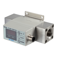
SMC Networks PF2W7 Series

SMC Networks PF2W7 Series
48 pages
To Next Page IconTo Next Page
Loading...
No.PF※※-OMO0012-D
PRODUCT NAME
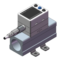
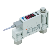
Digital Flow Switch
(Integrated display type)
MODEL / Series / Product Number
PF2W7##

Questions and Answers:

SMC Networks PF2W7 Series Specifications

General IconGeneral
BrandSMC Networks
ModelPF2W7 Series
CategorySwitch
LanguageEnglish

Summary

Safety Instructions

Limited Warranty and Compliance

Details product warranty period, disclaimers, and compliance requirements.

General Safety Warnings

Lists specific cautionary notes and hazard warnings for product usage.

Operator Safety Guidelines

Emphasizes the need for trained personnel and safe operation practices.

Product Handling, Environment, and Specifications

Covers product specifications, environmental restrictions, and general handling precautions.

Product Handling and Installation

Installation Guidelines

Covers mounting, tightening torque, and shock prevention.

Piping Connection Rules

Details on fluid direction, piping size changes, and preventing foreign matter.

Operating Environment and Adjustment

Environmental Considerations

Discusses restrictions on water, corrosive gases, oils, surges, vibration, and temperature.

Adjustment and Operation Basics

Covers load connection, operation modes, setting procedures, and Karman vortex principle.

Maintenance and Support

Maintenance and Inspection

Outlines regular maintenance, safety checks before work, and cleaning instructions.

Model Indication and Ordering

Order Specification Details

Explains model structure, flow ranges, temperature specs, and output options.

Lead Wire and Made-to-Order Options

Refers to lead wire options and made-to-order configurations.

Lead Wire and Accessory Part Numbers

Details lead wire types and part numbers for accessories like brackets.

Product Part Identification

Main Body Components Overview

Identifies main body parts, ports, bracket, and connector pin configuration.

Monitor Unit Features

Details the monitor, display, indicator LEDs, and control buttons.

Technical Definitions and Terminology

Flow Measurement Terminology

Defines terms like Accumulated flow, Instantaneous flow, and Karman vortex.

Switch Output and Control Terminology

Defines terms like Hysteresis, Hysteresis mode, and Switch output.

Performance and Operational Terminology

Defines terms like Proof pressure, Response time, and Unit selection function.

Mounting and Installation

Product Mounting Guidelines

Covers correct installation practices, monitor rotation, and bracket mounting.

Installing the Product

Details using the supplied screws and bracket for mounting.

Piping Connections

Piping Guidelines and Best Practices

Covers operating pressure, fluid direction, straight piping sections, and avoiding bubbles.

Connecting Piping and Torque Requirements

Details tightening torque for piping attachments and correct spanner usage.

Electrical Wiring

Wiring Connections and Safety Precautions

Covers connecting the lead wire, connector, and ensuring proper insulation.

Connector Pinout and Wire Colors

Shows pin assignments and wire color coding for the lead wire connector.

Internal Circuit Wiring Examples

Provides wiring diagrams for NPN and PNP output types with analogue signals.

Settings and Configuration Modes

Measurement Mode Overview

Describes the primary mode for flow detection and display.

Initialize Mode Settings

Allows setting of display mode, unit selection, and output configurations.

Function Selection Mode Settings

Enables inputting set values for instantaneous and accumulated outputs.

Key-Lock Function

Prevents unintentional changes to set values by locking the control keys.

Output Modes and Settings

Switch Output Diagrams

Illustrates output behavior for instantaneous and accumulated flow in different modes.

Initialize Mode Setup

Default Settings Overview

Lists default values for display, unit, output modes, and switch operations.

Setting Display and Unit Selection

Procedures for setting the display mode and selecting units (L/min or gal/min).

Setting Output Modes (OUT1 OUT2)

Procedures for configuring output modes for OUT1 and OUT2 (instantaneous, accumulated, pulse).

Setting Switch Operation (OUT1 OUT2)

Procedures for selecting reverse or non-reverse output operation for OUT1 and OUT2.

Flow Specifications with Unit Selection

Gal(US) Unit Flow Specifications

Details flow ranges and display units when using US gallons.

Function Selection Mode Operations

Default Set Values

Lists default input values for instantaneous and accumulated output set points.

Setting Instantaneous Output Values (F1)

Setting Set Points for OUT1

Manual procedure to set the first and second set points for the OUT1 output.

Setting Set Points for OUT2

Manual procedure to set the first and second set points for the OUT2 output.

Auto-Preset Output Value (F2)

Auto-Set Value for OUT1

Procedure to automatically set the output value for OUT1 based on actual flow.

Auto-Set Value for OUT2

Procedure to automatically set the output value for OUT2 based on actual flow.

Setting Accumulated Output Values (F3)

Setting Accumulated Values for OUT1

Manual procedure to set lower and upper digits for accumulated output (OUT1).

Setting Accumulated Values for OUT2

Manual procedure to set lower and upper digits for accumulated output (OUT2).

Managing Accumulated Flow Rate

Starting and Resetting Accumulation

How to start, stop, and reset the accumulated flow rate display.

Key-Lock Functionality

Locking and Unlocking the Control Keys

Step-by-step guide to lock and unlock the product's control buttons.

Maintenance and Power Interruption

Resetting After Power Loss

Explains how settings are retained and the need for safety checks after power interruptions.

Troubleshooting Common Faults

Display Issues and Resolution

Guides for resolving display errors like OFF, unstable, or incorrect readings.

Output and Piping Related Issues

Addresses faults related to output instability, leakage, and incorrect piping direction.

Error Indication and Troubleshooting

Interpreting Error Displays

Explains error codes for excessive flow, over current, system errors, and accumulated flow.

Product Specifications

Performance and Electrical Specs

Details flow ranges, pressure, output modes, load, voltage, and response time.

Environmental and Physical Specs

Covers enclosure, temperature, humidity, standards, materials, and weight.

Lead Wire Specifications

Specifies dimensions and materials for the lead wire and connector.

Performance Characteristics Data

Flow vs. Pressure Loss Characteristics

Graph illustrating pressure loss relative to flow rate for different models.

Ethylene Glycol Fluid Compatibility

Graph showing measurable concentration and temperature ranges for ethylene glycol.

Product Dimensions

PF2 W704720 Model Dimensions

Provides detailed dimensional drawings for PF2W704 and PF2W720 models.

PF2 W740 Model Dimensions

Provides detailed dimensional drawings for the PF2W740 model.

PF2 W711 Model Dimensions

Provides detailed dimensional drawings for the PF2W711 model.

PF2 W704 T720 T740 T Dimensions

Provides detailed dimensional drawings for PF2W704T, PF2W720T, and PF2W740T models.

Accessories and Mounting Brackets

Lead Wire and Connector Details

Details specifications for straight and right-angle lead wires and connectors.

Mounting Bracket Specifications

Provides dimensional information for various mounting brackets.

Customization and Analogue Output

Made-to-Order Configuration Options

Details on ordering specific product configurations and their part numbers.

Analogue Output Specifications and Behavior

Explains analogue output types, impedance, accuracy, and behavior with flow rates.

Document Management

Revision History Notes

Records changes made to the manual across different revisions.

Related product manuals