-29-
No.PF※※-OMO0012-D
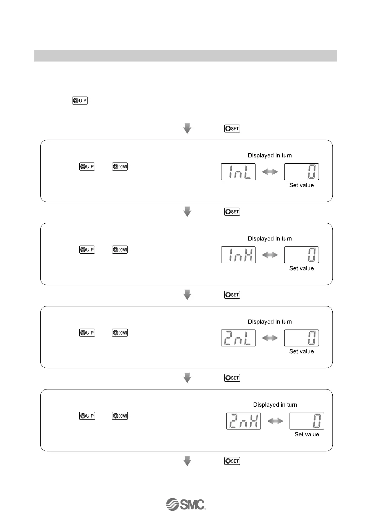
■[F_3] Input procedure of the Set value of accumulated output
The Set point of the switch output can be manually set. Accumulated flow rate is displayed by the lower 3
digits and upper 3 digits separately. Setting is performed separately.
<Operation>
Press the button in function selection mode to display [F_3]. (When both OUT1 and OUT2 are
assigned to be instantaneous output mode or accumulated output mode, [F_3] is not displayed. When
OUT1 or OUT2 is assigned to be accumulated output mode, [F_3] is displayed.)
Press the button.
Input of the Set value for the lower 3 digits (OUT1)
[1nL]
and the current Set value are displayed in turn.
Press the
and
button to change the value
referring the list of outputs (page 21).
: When Non-Reverse output is selected as the switch operation, [1PL]
is displayed.
Input of the Set value for the upper 3 digits (OUT1)
[1nH]
and the current Set value are displayed in turn.
Press the
and
button to change the value
referring the list of outputs (page 21).
: When Non-Reverse output is selected as the switch operation, [1PH]
is displayed.
Input of the Set value for the lower 3 digits (OUT2)
[2nL ]
and the current Set value are displayed in turn.
Press the
and
button to change the value
referring the list of outputs (page 21).
: When Non-Reverse output is selected as the switch operation, [2PL]
is displayed.
Input of the Set value for the upper 3 digits (OUT2)
[2nH]
and the current Set value are displayed in turn.
Press the
and
button to change the value
referring the list of outputs (page 21).
: When Non-Reverse output is selected as the switch operation, [2PH]
is displayed.
Press the button. (continued)
 Loading...