EasyManua.ls Logo

SMC Networks PF2M7 Series - User Manual

Default Icon
80 pages
Print Icon
To Next Page IconTo Next Page
Loading...
No.PF※※-OMW0007-A
PRODUCT NAME
Digital Flow Switch
(Integrated display type)
MODEL / Series / Product Number
PF2M7##

Other manuals for SMC Networks PF2M7 Series

Questions and Answers

  • S
    Stephanie EllisAug 17, 2025
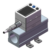
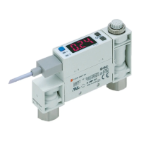
    What to do if there is no output from my SMC Networks PF2M7?
    • J
      jamiepalmerAug 17, 2025
      If your SMC Networks Switch displays no output, several factors could be responsible. First, ensure that the wiring is correct and that the connector is properly connected. If the output is unstable, try installing a filter or mist separator on the IN side, and remove any foreign matter from the mesh, being careful not to damage the product. Also, check that the piping is installed in the correct direction, matching the arrow on the body. If the flow is pulsing, consider switching to a pressure source with less fluctuation or installing a tank to reduce pressure fluctuation. Finally, make sure there are no air leaks and correct the piping if necessary. If the hysteresis value is too low, increase the hysteresis set value.
  • R
    Richard RodriguezAug 20, 2025
    How to troubleshoot no display on SMC Networks Switch?
    • P
      Patricia MillerAug 20, 2025
      If your SMC Networks Switch isn't displaying anything, start by checking the wiring and connectors to make sure they are correctly connected. If you have selected peak/bottom value display mode, refer to "Peak/bottom value display" (page 55) and remove that setting. If the display is unstable, install a filter or mist separator on the IN side and remove any foreign matter on the mesh, being careful not to damage the product. Ensure the piping is connected correctly, matching the flow direction arrow on the body. If the flow is pulsing, switch to a pressure source with less fluctuation, or install a tank. Finally, correct any air leakage by fixing the piping.
  • M
    Mrs. Tara HuangAug 22, 2025
    Why is my SMC Networks PF2M7 displaying incorrectly?
    • J
      Jonathan WoodsAug 23, 2025
      If your SMC Networks Switch shows an incorrect display, it might be due to several reasons. Foreign matter could have entered the flow passage or adhered to the sensor, so install a filter or mist separator on the IN side and clean any foreign matter from the mesh, being careful not to damage the product. Ensure the piping is not reversed by mounting the product so the flow direction matches the arrow on the body. Also, verify that the correct unit is selected using the unit selection function. Finally, check for and correct any air leaks in the piping.
  • M
    Michael ZamoraAug 26, 2025
    What to do if the flow adjustment valve fails to adjust the flow on my SMC Networks PF2M7 Switch?
    • J
      Joshua MartinezAug 26, 2025
      If the flow adjustment valve on your SMC Networks Switch fails to adjust the flow, the valve might be locked. Loosen the lock ring, and then adjust the flow adjustment valve.
  • J
    Joshua HamiltonAug 28, 2025
    What to do if there is no reaction when the buttons are pressed on SMC Networks PF2M7 Switch?
    • J
      James ScottAug 28, 2025
      If the buttons on your SMC Networks Switch are not responding, the keys may be locked. To resolve this, release the key-lock function. (page 57)
  • C
    coxbrandonAug 30, 2025
    What to do if the flow does not start on my SMC Networks PF2M7 Switch?
    • C
      Crystal PerezAug 31, 2025
      If your SMC Networks Switch's flow does not start, the flow adjustment valve might be locked. Loosen the lock ring before attempting any adjustments.
  • E
    Edward MartinSep 2, 2025
    How to fix instantaneous flow error on SMC Networks PF2M7?
    • A
      Angela MarshallSep 3, 2025
      To resolve an instantaneous flow error on your SMC Networks Switch, reduce the flow and ensure that the flow is in the correct direction.
  • K
    Kimberly DiazSep 5, 2025
    How to fix OUT1 over current error on SMC Networks PF2M7 Switch?
    • K
      Kayla BruceSep 5, 2025
      To resolve an OUT1 over current error on your SMC Networks Switch, turn the power off, identify and remove the cause of the over current, and then turn the power back on.
  • D
    Donald MorganSep 8, 2025
    What to do for zero clear error on SMC Networks Switch?
    • H
      hayslindaSep 8, 2025
      To resolve a zero clear error on your SMC Networks Switch, retry the zero clear operation without applying any fluid.
  • L
    Lauren GibsonSep 12, 2025
    How to resolve system error on SMC Networks Switch?
    • M
      Matthew FisherSep 12, 2025
      To address a system error on your SMC Networks Switch, turn the power off and then turn it back on again.

Summary

Safety Instructions

Hazard Level Definitions

Explains the meaning of Caution, Warning, and Danger labels used in the manual.

General Safety Guidelines

Outlines operator responsibilities, training requirements, and service precautions.

Special Application Considerations

Lists conditions requiring special safety measures and analysis, like hazardous environments.

Limited Warranty and Compliance

Details the product warranty period, terms, and restrictions on use for weapons or export.

Product Handling and Operation

Operator Qualifications and Responsibilities

Specifies that only trained personnel should operate the equipment safely.

Critical Operation Warnings

Warns against disassembly, operating outside specifications, and use in hazardous atmospheres.

Installation Guidelines

Covers stress, grounding, shock, wire handling, dust, orientation, and foreign matter prevention.

Wiring Best Practices

Provides guidance on lead wire handling, correct wiring, insulation, and noise prevention.

Environmental Operating Conditions

Details restrictions on use in corrosive environments, high vibration, magnetic fields, and temperature extremes.

Adjustment and Maintenance

Covers setting procedures, regular maintenance, and cleaning recommendations.

Model Indication and Ordering

Model Nomenclature and Flow Ranges

Explains how to interpret the product model code and available flow ranges.

Output Specifications and Options

Details available output types, unit specifications, and product options.

Accessories and Part Numbers

Ordering Specific Accessories

Lists part numbers for lead wires, connectors, adapters, and mounting brackets.

Product Components Overview

Body Component Identification

Identifies and describes the main body parts of the flow switch.

Display and Control Interface

Explains the function of the display screen, buttons, and LEDs.

Technical Terminology Definitions

Flow Measurement Concepts

Defines terms like Accumulated flow, Instantaneous flow, Hysteresis, and Digital filter.

Output and Signal Characteristics

Defines terms related to Analogue output, Switch output, and impedance.

Operational and System Terms

Defines terms such as Key-lock, Unit selection, and Withstand voltage.

Mounting and Installation

Panel Mounting Procedure

Details how to mount the product onto a panel using adapters.

Bracket and DIN Rail Mounting

Explains mounting with brackets or on DIN rails and required torque.

Wiring and Connections

Connector Wiring and Disconnection

Covers safe connection and disconnection of the electrical connector.

Internal Circuit and Wiring Examples

Provides schematic diagrams for NPN and PNP output configurations.

Settings Configuration Overview

Navigating Setting Modes

Introduces measurement, simple setting, and function selection modes.

Flow and Hysteresis Setting

Explains how to set flow rate thresholds and hysteresis for outputs.

Function Setting Mode Access

Details how to enter the function selection mode for advanced settings.

Default Settings Reference

Function Default Value Summary

Provides a table listing default settings for all configurable functions.

F0: Fluid;Units Criteria;Measurement Unit Setting

Setting Operating Fluid

Allows selection of the fluid type (e.g., Air, N2, Ar, CO2).

Setting Units Criteria and Measurement Units

Configures reference conditions and display units (e.g., L/min, CFM).

F1: Setting of OUT1

Output Mode Configuration

Selects output behavior like hysteresis, window comparator, or accumulated output.

Output Type and Display Color

Sets normal/reversed output and display color linked to output status.

Count-Up;Down Display and Flow Setting

Configures counting display and sets the primary flow value for OUT1.

Hysteresis and Delay Time Settings

Adjusts hysteresis for output stability and delay time for signal response.

Display Color Settings for OUT1

Defines display colors for ON/OFF states of OUT1.

List of Output Modes

Output Mode Behavior Diagrams

Illustrates normal, reversed, window comparator, accumulated, and error output modes.

F2: Setting of OUT2

Output Mode Configuration for OUT2

Sets output behavior for OUT2 similar to OUT1 configuration.

Output Type and Display Color for OUT2

Configures normal/reversed output and display colors for OUT2.

Count-Up;Down Display and Flow Setting for OUT2

Configures counting display and sets the primary flow value for OUT2.

Hysteresis and Delay Time for OUT2

Adjusts hysteresis and delay time settings specific to OUT2.

Display Color Settings for OUT2

Defines display colors for ON/OFF states of OUT2.

F3: Digital Filter Setting

Setting Digital Filter Time

Selects digital filter time to reduce flow measurement fluctuation.

F4: Auto-Preset Function Setting

Enabling Auto-Preset Function

Allows automatic calculation and setting of optimum values based on operating conditions.

Auto-Preset Operation Guide

Details the step-by-step process for performing auto-preset for OUT1 and OUT2.

F10: Display Mode Setting

Selecting Displayed Flow Type

Chooses between displaying instantaneous or accumulated flow rate.

F11: Display Resolution Setting

Adjusting Display Resolution

Changes the minimum setting unit for flow display on specific models.

F13: Setting for Reverse Display Mode

Enabling Reverse Display Function

Allows changing the display orientation for easier operation.

F14: Zero Cut-Off Setting

Setting Zero Cut-Off Function

Forces zero display to remove flickering at the lower flow limit.

Checking Zero Cut-Off Value

Verifies the set zero cut-off percentage and allows resetting.

F22: Analogue Output and Free Span Setting

Setting Analogue Output Type

Configures voltage (1-5V, 0-10V) or current (4-20mA) analogue output.

Setting Analogue Free Span

Enables or disables the analogue free span function for output calibration.

Inputting Set Value for Analogue Output

Sets the flow value corresponding to specific analogue output signals (e.g., 5V, 20mA).

F30: Accumulated Flow Value Hold Setting

Configuring Accumulated Flow Hold

Sets how long the accumulated flow value is held after power is supplied.

F80: Display OFF Mode Setting

Activating Display OFF Mode

Configures the display to turn off automatically after a period of inactivity.

F81: Security Code Setting

Enabling;Disabling Security Code

Turns the security code function ON or OFF.

Setting and Checking Security Code

Guides on how to set, change, and verify the security code.

F90: Setting of All Functions

Managing All Function Settings

Allows enabling or disabling all function settings simultaneously.

F98: Output Check Setting

Performing Output Checks

Allows manual checking of switch and analogue outputs by turning them ON/OFF.

F99: Reset to Default Settings

Restoring Factory Defaults

Resets all product settings to their original factory default values.

Other Settings and Features

Snap Shot and Peak;Bottom Value Indication

Captures current flow values and displays peak/minimum readings.

Reset and Zero-Clear Functions

Resets accumulated flow and clears the displayed flow value to zero.

Key-Lock Functionality

Prevents unintentional changes to set values by locking the keypad.

Key-Lock Operation (Without Security Code)

Explains how to lock/unlock the keypad without requiring a security code.

Key-Lock Operation (With Security Code)

Details locking and unlocking the keypad using a security code.

Inputting and Changing Security Code

Provides instructions on how to enter and modify the security code.

Maintenance and Support

Product Maintenance Considerations

Discusses product behavior after power loss and general maintenance.

Forgotten Security Code Procedure

Outlines steps to recover access if the security code is lost.

Troubleshooting Common Issues

Display Problems and Solutions

Addresses issues like no display, unstable display, and incorrect readings.

Output and Button Issues

Covers problems with output stability, no reaction to buttons, and flow adjustment.

Error Indication Codes

Flow and Current Error Codes

Explains errors related to instantaneous flow limits and over current on outputs.

System and Accumulated Flow Errors

Details system errors and accumulated flow range errors.

Technical Specifications

Fluid, Flow Rate, and Pressure Specifications

Lists details on applicable fluids, flow ranges, and pressure ratings.

Electrical and Switch Output Specifications

Covers power supply, current consumption, output types, and response times.

Analogue Output, Display, and Environmental Specs

Details analogue output impedance, display types, and environmental resistance.

Standards, Piping, and Weight

Lists certifications, piping specifications, and component weights.

Performance Characteristics Data

Flow Rate vs. Analogue Output

Shows relationships between flow rates and analogue output signals.

Flow Adjustment and Pressure Loss Data

Provides reference data on flow adjustment needle rotation and pressure loss.

Flow Characteristics at Negative Pressure

Illustrates flow behavior under negative pressure conditions.

Product Dimensions

Dimensions for PF2 M710;725;750-C6 Models

Shows the physical dimensions and connection points for specific models.

Dimensions for PF2 M710;725;750 S-C6 Models

Provides dimensional details for variants with 'S' designation.

Dimensions for PF2 M711-C8 Models

Shows the physical dimensions for the PF2M711 model with C8 port size.

Dimensions for PF2 M711 S-C8 Models

Provides dimensional details for the PF2M711S model with C8 port size.

Panel Cut-out and Bracket Dimensions

Gives dimensions for panel mounting cut-outs and accessory brackets.

SMC Networks PF2M7 Series Specifications

General IconGeneral
Number of Ports7
Switching Capacity1.4 Gbps
Power over Ethernet (PoE)No
Form FactorDesktop
Forwarding Rate1 Mpps
Jumbo Frame SupportNo
Port Type10/100 Mbps Ethernet
Power SupplyExternal
Product TypeEthernet Switch
Ports7 x 10/100Base-TX

Related product manuals