EasyManua.ls Logo

SMC Networks PFM7 Series - User Manual

SMC Networks PFM7 Series
78 pages
Print Icon
To Next Page IconTo Next Page
Loading...
No.PF※※-OMJ0006-G
PRODUCT NAME
Digital Flow Switch
(Integrated display type)
MODEL / Series / Product Number
PFM7##

Questions and Answers

  • S
    Samuel ArellanoAug 19, 2025
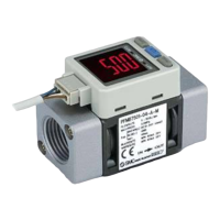
    What to do if SMC Networks PFM7 has incorrect output?
    • R
      Robert JohnsonAug 19, 2025
      If your SMC Networks Switch is showing an incorrect output, several issues could be the cause. Check for incorrect wiring or a disconnected connector and correct them. Foreign matter in the flow passage or adhered to the sensor can also cause this problem; in that case, install a filter or mist separator on the IN side. Ensure the piping is correctly installed so that the fluid flow matches the direction marked on the product body. If the flow is pulsing, install an accumulator tank to reduce the pressure fluctuation or change the pressure source to one with less pulsation. Air leakage might be the reason, so reconnect the piping with the specified tightening torque and re-apply the sealant tape. Also, check if the hysteresis value is too low and increase the hysteresis set value.
  • J
    Jason BuckAug 22, 2025
    How to fix incorrect operation of the flow adjustment valve on SMC Networks Switch?
    • R
      Robert HernandezAug 22, 2025
      If the flow adjustment valve on your SMC Networks Switch is not operating correctly, it might be locked. Loosen the lock ring and then adjust the flow adjustment valve. Alternatively, the supply pressure may be insufficient; in this case, increase the supply pressure.
  • J
    jessicakerrAug 26, 2025
    Why fluid does not flow in SMC Networks PFM7 Switch?
    • S
      sanchezmartinAug 26, 2025
      If fluid isn't flowing in your SMC Networks Switch, the flow adjustment valve might be closed. Open the flow adjustment valve and adjust the flow.
  • L
    Lisa PrattAug 28, 2025
    What to do if external input does not operate on SMC Networks Switch?
    • W
      Whitney SullivanAug 28, 2025
      If the external input on your SMC Networks Switch isn't working, first check for incorrect wiring and correct it. Also, the input signal duration might be too short; for external inputs, ensure the white wire is connected to GND for 30 ms or more.
  • F
    fbeckAug 31, 2025
    How to unlock buttons on SMC Networks PFM7 Switch?
    • D
      Devin SilvaAug 31, 2025
      If the buttons on your SMC Networks Switch are not operating, the keys may be locked. Release the key-lock function. (Refer to 46)
  • T
    Tyler GonzalezSep 3, 2025
    How to resolve over current error on SMC Networks PFM7?
    • N
      Nathan ParkerSep 3, 2025
      To fix an over current error on your SMC Networks Switch, turn off the power supply and remove the cause of the over current. Then, supply the power again.
  • R
    Ronnie WalkerSep 6, 2025
    What to do for system error on SMC Networks PFM7?
    • C
      Catherine OrtizSep 6, 2025
      To address a system error on your SMC Networks Switch: * Stop operation immediately and contact SMC. * Turn the power off and turn it on again, then repeat the Function Setting.
  • S
    Stephanie MartinezSep 9, 2025
    How to resolve zero clear error on SMC Networks PFM7 Switch?
    • J
      Jose RichardsSep 9, 2025
      To resolve a zero clear error on your SMC Networks Switch, perform the zero clear function again under no flow conditions.
  • E
    Edwin MyersSep 12, 2025
    How to resolve accumulated flow error on SMC Networks PFM7?
    • A
      amitchellSep 12, 2025
      To resolve an accumulated flow error on your SMC Networks Switch, reset the accumulated flow by pressing the and buttons simultaneously for 1 second or more.
  • C
    Charles MccoyNov 15, 2025
    Why is my SMC Networks PFM7 display incorrect?
    • S
      Stacey ParsonsNov 15, 2025
      An incorrect display on your SMC Networks Switch can be caused by several factors. It could be due to incorrect wiring or a loose connector; in these cases, correct the wiring or the connector wiring. If the peak/bottom value display mode is selected, refer to "Peak/bottom value display" (page 45), and remove the setting. Foreign matter in the flow passage or adhered to the sensor may also cause this, so install a filter or mist separator on the IN side. Ensure the piping is correctly connected so that the fluid flow matches the direction marked on the product body. Pulsing flow can also lead to display issues, so install an accumulator tank to reduce pressure fluctuation or change the pressure source to one with less pulsation. Finally, check that the display units setting and the selecte...

Summary

Safety Instructions

Hazard Level Definitions

Defines hazard levels: Caution, Warning, and Danger.

Product Compatibility Responsibility

Responsibility for product compatibility with equipment lies with the designer.

Trained Personnel for Operation

Only appropriately trained personnel should operate machinery and equipment.

Safety Confirmation Before Service

Do not service or remove product until safety is confirmed.

Special Safety Considerations

Special safety measures required for certain operating conditions.

Limited Warranty and Disclaimer

Outlines the terms and conditions of the product warranty and disclaimers.

Compliance Requirements

Details compliance requirements for product use and export.

General Warning

Key safety warnings including disassembly, unauthorized repair, and operation outside specifications.

Terminal and Connector Caution

Caution regarding touching terminals and connectors while power is on.

Product Design and Selection Guidelines

Notes on product design, selection, and handling, including power supply and voltage specifications.

Product Handling and Installation Precautions

Guidelines for handling the product and installation, including torque and mounting.

Wiring Guidelines

Important points for correct wiring, avoiding noise, and cable management.

Environmental Considerations

Guidelines for product usage in various environmental conditions like corrosive gases, surges, and temperature.

Model Indication and How to Order

Model Configuration Options

Guide to selecting product model parameters like flow range, output, and fittings.

Option 1 and Option 2 Details

Specific configurations for product options including lead wires and mounting accessories.

Made to Order

Special Piping Combinations

Customization options for inlet and outlet piping directions.

Accessories and Part Numbers

List of part numbers for separately ordering accessories.

Summary of Product Parts

Component Identification

Overview of product components like LEDs, buttons, ports, and display.

Mounting and Installation

Panel Mounting Procedures

Steps for mounting the product onto a panel using adapters.

Bracket and DIN Rail Mounting

Instructions for mounting the product using brackets or DIN rails.

Piping

Metal Piping Attachment Installation

Guidelines for attaching metal pipes, including torque and sealing.

One-Touch Fitting Installation

Procedures for installing one-touch fittings for piping connections.

Wiring

Connector Wiring and Pinout

Details on connecting the electrical connector and pin assignments.

Output Type Wiring Examples

Wiring diagrams for various output types (NPN, PNP, Analogue, External Input).

Flow Setting

Measurement Mode Operation

Describes the sequence of displays upon power supply in measurement mode.

Switch Operation Logic

Explains how the switch operates based on flow rate and hysteresis.

Setting Output Values

Steps to set output values and clear the display.

Function Setting

Function Selection Mode

How to enter and exit the function selection mode.

Default Settings Overview

Table listing default settings for various functions (F0 to F99).

[F 0] Unit Selection Function

How to select units for display (L/min or CFM).

[F1] Setting of OUT1

How to set the output mode and reversed output for OUT1.

[F2] Setting of OUT2

How to set the output method for OUT2.

[F3] Operating Fluid Selection

Setting the type of operating fluid (Air, N2, Ar, CO2).

[F4] Reference Condition Selection

Selecting standard or normal condition for reference.

[F5] Response Time Setting

Adjusting the response time of the switch output.

[F6] Display Mode Selection

Choosing between instantaneous or accumulated flow display.

[F7] External Input Configuration

Setting up external input functions like reset and auto-shift.

Auto-Shift Functionality

Detailed explanation and examples of auto-shift and auto-shift zero functions.

[F8] Display Resolution Setting

Adjusting display resolution for 10 and 100 L/min types.

[F9] Auto-Preset Function

Automatic calculation of approximate set values based on operation.

[F10] Accumulated Value Hold

Function to store accumulated flow values in permanent memory.

[F11] Analogue Output Filter

Setting for filtering analogue output signals.

[F12] Power Saving Mode

Enabling power saving mode to reduce power consumption.

[F13] Security Code Function

Setting a security code to lock/unlock the keys.

[F98] Setting of All Functions

Allows sequential setting of all functions.

[F99] Reset to Default Settings

Restoring the product to its factory default settings.

Other Settings

Peak;Bottom Value Display

Displaying maximum and minimum instantaneous flow values.

Zero Clear Function

Adjusting the displayed value to zero.

Key-Lock Function

Prevents unintentional changes to set values by locking the keys.

Changing Security Code

Procedure to change the existing security code.

Maintenance

Reset After Power Loss

How to reset the product after a power cut or de-energizing.

Troubleshooting

Faults and Countermeasures

Table of common faults, possible causes, and solutions.

Troubleshooting Other Issues

Faults related to buttons, flow adjustment valve, and external input.

Error Indication

Error Code Explanations

Details on flow error, over current error, system error, and accumulated flow error.

Specifications

General Specifications

Details on applicable fluid, flow ranges, and operating conditions.

Output and Environment Specs

Specifications for output types, environment, and standards.

Piping Port Specifications

Cable Specifications

Details on cable conductor, insulator, and sheath.

Characteristics Data

Analogue Output Characteristics

Graphs showing analogue output voltage and current characteristics.

Flow Adjustment Characteristics

Graphs showing flow characteristics versus needle revolution.

Pressure Loss Characteristics

Graphs illustrating pressure loss at various flow rates.

Dimensions

PFM7-(N)01;(N)02;F01 Dimensions

Dimensional drawings for specific PFM7 models.

PFM7-(N)01 L;(N)02 L;F01 L Dimensions

Dimensional drawings for specific PFM7L models.

PFM7 S-(N)01;(N)02;F01 Dimensions

Dimensional drawings for specific PFM7S models.

PFM7 S-(N)01 L;(N)02 L;F01 L Dimensions

Dimensional drawings for specific PFM7SL models.

PFM7□-F02 Dimensions

Dimensional drawings for specific PFM7F02 models.

PFM7□-F02 L Dimensions

Dimensional drawings for specific PFM7F02L models.

PFM7□S-F02 Dimensions

Dimensional drawings for specific PFM7SF02 models.

PFM7□S-F02 L Dimensions

Dimensional drawings for specific PFM7SF02L models.

PFM7□-C4;C6;C8;N7 Dimensions

Dimensional drawings for PFM7 with C4/C6/C8/N7 fittings.

PFM7□-C4 L;C6 L;C8 L;N7 L Dimensions

Dimensional drawings for PFM7L with C4L/C6L/C8L/N7L fittings.

PFM7□S-C4;C6;C8;N7 Dimensions

Dimensional drawings for PFM7S with C4/C6/C8/N7 fittings.

PFM7□S-C4 L;C6 L;C8 L;N7 L Dimensions

Dimensional drawings for PFM7SL with C4L/C6L/C8L/N7L fittings.

Panel Cut-out Dimensions

Dimensions required for panel cut-outs for mounting.

Bracket Dimensions

Dimensional drawings for mounting brackets.

Made to Order Special Combinations

PFM7 Custom Piping Diagrams

Diagrams showing custom piping for PFM7 models.

Gas Mixture Settings

Gas Mixture Selection Function ([F97])

Setting the ratio of Argon and Carbon Dioxide gas mixtures.

Gas Mixture Specifications

Flow and Output Details

Flow ranges and analogue output based on gas mixture selection.

SMC Networks PFM7 Series Specifications

General IconGeneral
BrandSMC Networks
ModelPFM7 Series
CategorySwitch
LanguageEnglish

Related product manuals