-19-
No.PF※※-OMW0007-A
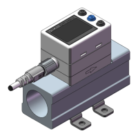
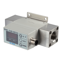
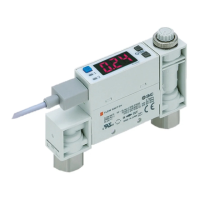
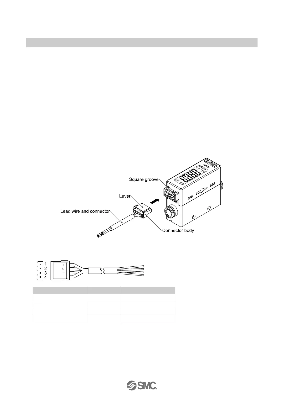
■Wiring
Wiring of connector
Connections should only be made with the power supply turned off.
Use separate routes for the product wiring and any power or high voltage wiring. Otherwise, malfunction
may result due to noise.
Ensure that the FG terminal is connected to ground when using a commercially available switch-mode
power supply. When a switch-mode power supply is connected to the product, switching noise will be
superimposed and the product specification can no longer be met. This can be prevented by inserting a
noise filter, such as a line noise filter and ferrite core, between the switch-mode power supply and the
product, or by using a series power supply instead of a switch-mode power supply.
Connecting/Disconnecting
When mounting the connector, insert it straight into the socket, holding the lever and connector body, and
push the connector until the lever hooks into the housing, and locks.
When removing the connector, press down the lever to release the hook from the housing and pull the
connector straight out.
Connector pin numbers (on the lead wire)
 Loading...