-18-
No.PF※※-OMW0007-A
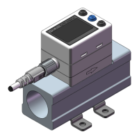
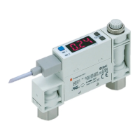
Bracket mounting
Mount the bracket using the mounting screws supplied.
The required tightening torque is 0.42±0.04 Nm.
Install the product (with bracket) using the M3 screws (4 pcs.).
Bracket thickness is approximately 1.2 mm.
Refer to the dimension drawing of the bracket (page 73) for mounting hole dimensions.
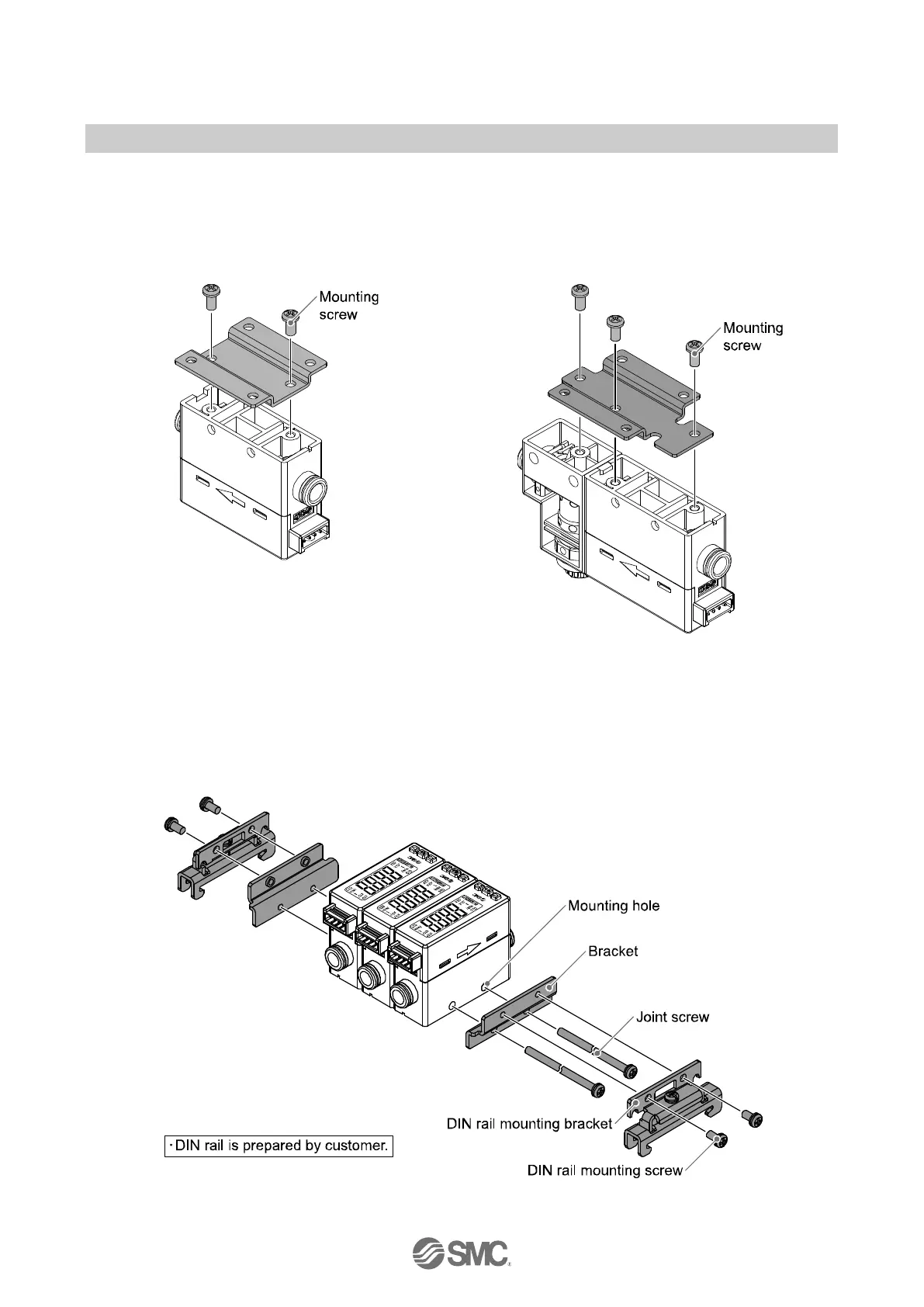
DIN rail mounting (using ZS-33-R#)
Mount the DIN rail mounting parts using DIN rail mounting screws and joint screws supplied.
The required tightening torque of the DIN rail mounting screws and joint screws is 0.4±0.05 Nm.
 Loading...