M
Michelle WrightSep 12, 2025
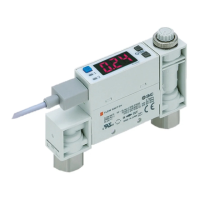
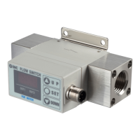
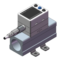
Why is the display flashing on my SMC Networks Switch?
- SStephanie RobbinsSep 12, 2025
If the display on your SMC Networks Switch flashes, it suggests there may be incorrect wiring. Check and correct the wiring to resolve this issue.