PTE-100-C
7
GENERAL OVERVIEW
Technology
The PTE-100-C combines state-of-the-art digital technology with the tradi-
tional regulation method based on a variable autotransformer and trans-
former.
Analogue and digital electronics convert signals in- and out from the unit in
order to be processed and displayed by an 8-bit microprocessor.
The power section is based mainly on electromechanical components.
The unit’s layout is arranged in modules and the number of moving parts is
kept to a minimum for easy and safe operation.
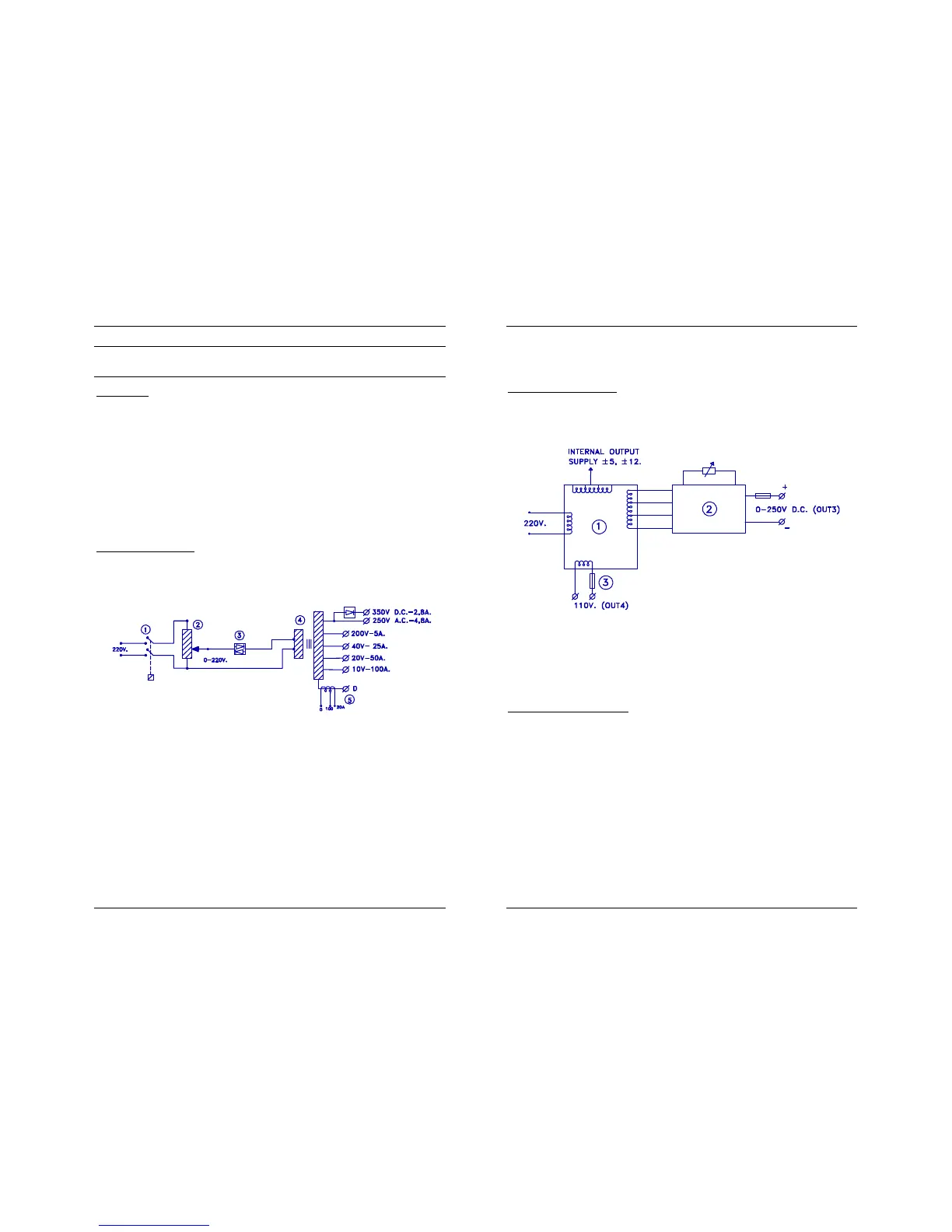
Power Section Design
Classical, direct regulation and transformers are used to generate and con-
trol the high 1,000-VA power output, as shown in the following diagram:
1. An internal relay connects the main power supply to the variac un-
der no-load conditions.
2. The single-phase variable autotransformer (Variac) regulates the
voltage at the primary winding of the output power transformer.
3. A static switch (Triac) guarantees a clean connection and discon-
nection of the Variac from the power transformer’s input.
4. A toroidal transformer guarantees the insulation of the output from
the main power supply.
5. A current measurement transformer, with one primary winding and
two secondaries with 250:1 and 50:1 respective ratios, is connect-
USER’S MANUAL
8
ed to the ‘zero’ output tap of the power transformer. Measurement
range switching is automatic.
Auxiliary Voltage Supply
By means of a transformer with multiple secondary windings, the PTE-100-C
features two independent auxiliary voltage outputs:
Out 3 is a variable 0-250 VDC stabilized, electronically protected
supply with a dedicated ON/OFF switch, and
Out 4 is a fixed 110 VAC. This fuse-protected output is permanent-
ly active whenever the equipment is switched on.
Measurement and Control
Analogue input is converted to digital values before it is processed and dis-
played. The following external or internal analogue magnitudes are meas-
ured:
Voltage.
Current.
Phase angle.
Temperature.
Displayed and/or used values like Impedance or Power are automatically
calculated from these magnitudes by the microcontroller.

 Loading...
