PTE-100-C
13
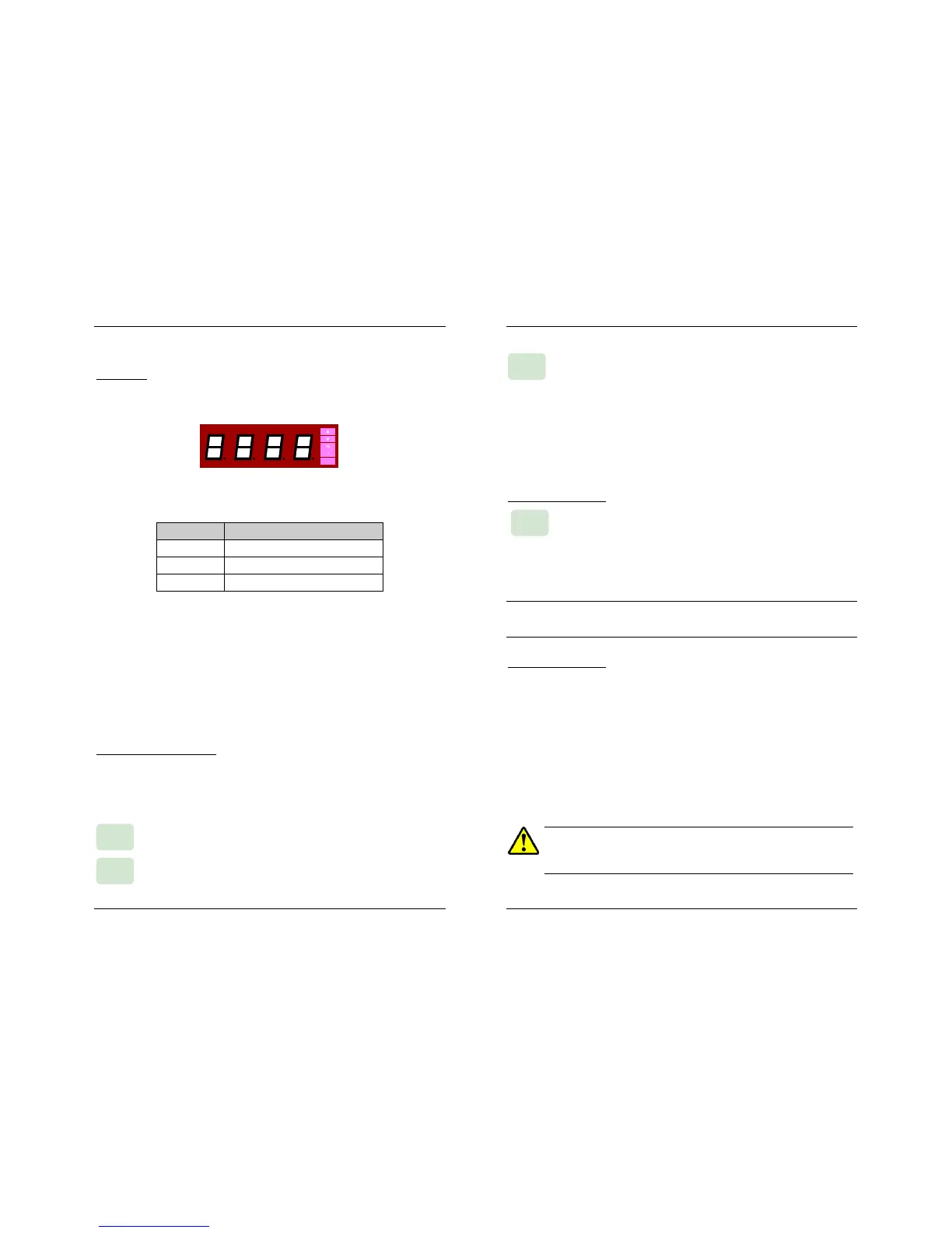
Display #2
All the PTE-100-C output magnitudes are shown on Display #2, located
above the variac’s knob:
The units in which the various possible readings are represented are labeled
on the right edge ot this LED display:
INDICATORS UNITS
A Current in Amps.
V Voltage in Volts.
% Percentage of the nominal current.
The following measurements can be read on this display:
Output current in Amperes.
AC or DC voltage present in Out 1 or Out 2 power taps and also
in Out 3 auxiliary DC voltage tap (regulated independently).
Percentage of the ‘nominal’ current value entered in Display #1 by
means of the “%” special function.
The floating decimal point is automatically placed to accommodate the
reading to the working regulation range.
Displaying the used output
Variable output magnitudes are shown in Display #2, used as an ammeter
by default. Since there are several output taps but only one display, you
need to select the tap to be displayed by pressing the corresponding display
assignment buttons:
Press this button to view the voltage present in Out 1 (variable
0-250 VAC).
Press this button to view the voltage present in Out 2 (variable
0-350 VDC).
Out 2
Out 1
USER’S MANUAL
14
Press this button to view the voltage present in Out 3 (auxiliary
variable 0-250 VDC). Out 3, located in the center section of
the PTE-100-C panel, is switched on, regulated and protected
independently from the other outputs.
A green LED above its tap will identify the displayed output. If you want to
lock the Display #2 to Out1, Out2 or Out3, press the corresponding dis-
play selection button and hold it for 5 seconds until you hear a beep. To
return to the normal ammeter function, give a brief press to any of these
buttons.
Current tap selection.
The PTE-100-C cannot detect which of the current taps is con-
nected the load to. Though the current value shown by Display
#2 is common to the four taps, some special functions, overload protections
and calculations require that the current output tab to which the load is
actually connected is identified to the unit. Press this key to sequentially sig-
nal the 100 A, 50 A, 25 A or 5 A tap in use.
Though this will not affect the output current nor the value shown in Display #2,
we strongly recommend you to do it whenever you move your connections to a
different current output.
Power Section Alarms
The PTE-100-C’s power section is protected form over-heating and from
overload. These conditions will automatically switch the power output off
and will be signaled by these two orange-colored 3-mm LEDs:
• I Therm. An internal sensor will protect the unit from overheating. This
alarm automatically disappears when the unit cools down to
normal temperature. Operation can then be resumed.
• I Lim. This protection operates when the upper limit of the selected
current tap, or the limit optionally set with the “Ilim” special
function, whichever is lowest, has been exceeded.

 Loading...
