PTE-100-C
17
SYMBOLS UNITS
S Seconds.
CY Cycles of the main AC supply line.
Hz Hertz (Frequency)
V Volts in a.c. (steady) or d.c. (flashing)
O Phase Angle Degrees.
Ω Ohms
VA Power in Volt amperes
A Amperes
The floating decimal point is automatically placed to accommodate the
reading to the working measurement range’s accuracy.
Timer control
The following buttons are used to control the PTE-100-C’s timer operation
and various start/stop logics:
Successive presses of this button change the start and stop modes
of the timer. The various options are represented by different
combinations of the START and STOP LEDs on the left side of the
button. Refer to the Timer Start and Stop Modes section below.
Use this button to toggle the displayed time between seconds and
cycles (of the power line’s frequency).
This button returns the timer to zero and re-enables the automatic
power shut off. Injection will not stop automatically upon relay
operation if the timer is not previously reset. Please refer to the
Operation section for a more in-depth description of this feature.
Timer start/stop modes
You can adapt yourself to different timing conditions by setting up the vari-
ous combinations of start and stop events for the PTE-100-C’s timer. The
default combination –first and third LEDs- sets the timer to start when the
current or voltage output are connected and to stop when operation is de-
tected at the monitor’s dry or wet contact inputs. Use the MODE button to
toggle between the available combinations:
Reset
Display
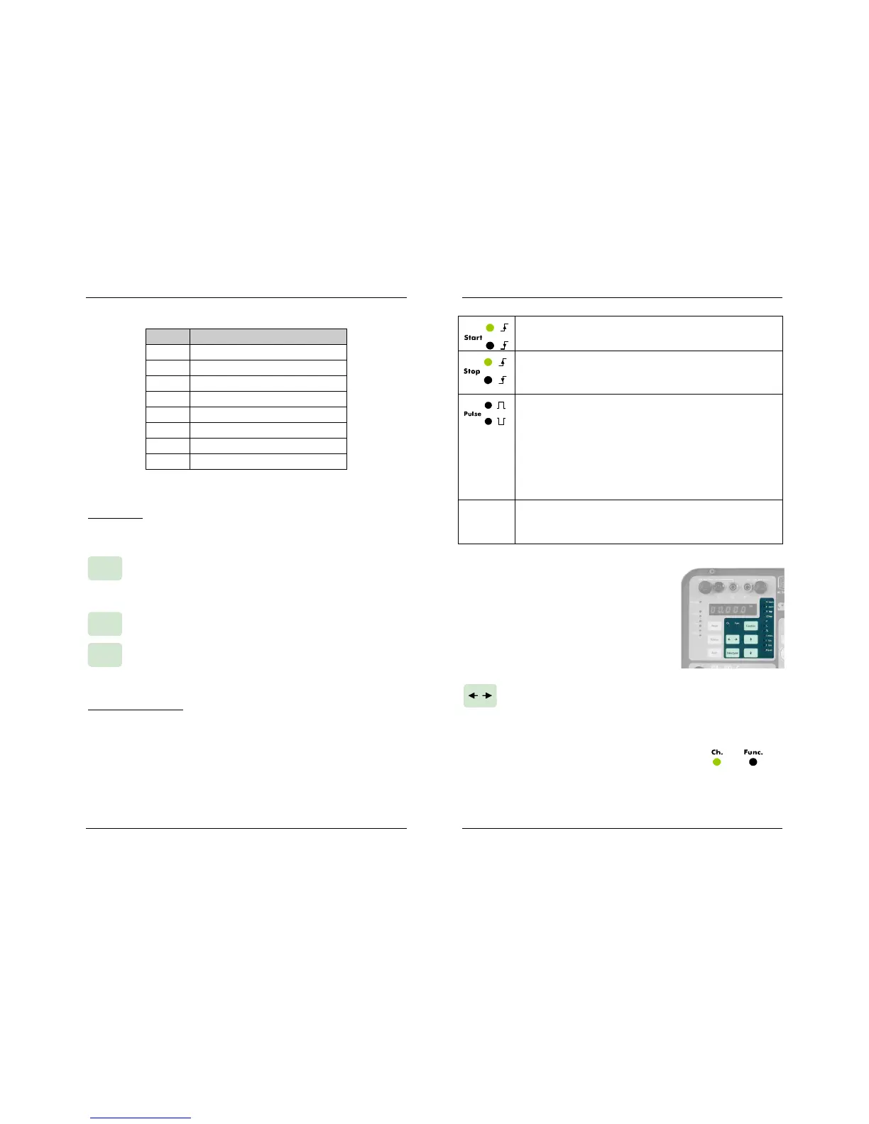
Upper LED: the timer will start when injection is switched on.
Lower LED: the timer will start when injection is switched off.
Upper LED: the timer will stop when the monitor is set to ac-
tive. Lower LED: the timer will stop when the monitor is set to
inactive.
Pulse mode measures the time elapsed between two opposite
monitor events.
Upper LED (positive pulse): The timer will start when a moni-
tor condition appears and will stop when it disappears.
Lower LED (negative pulse): The timer will start when an exist-
ing monitor condition disappears and will stop when it comes
back.
Monitor
Monitor detection occurs when a contact is closed between
the BLACK/GREEN or a voltage appears between the
BLACK/RED monitor input connectors.
SPECIAL FUNCTIONS
The following buttons provide access to the spe-
cial measurement and control functions grouped
in the shaded area underneath Display #1.
These functions are provided to complement the
main unit’s features and to simplify frequent in-
field operations.
Press this button to access or exit the special functions listed be-
low. When done, press it again for normal operation. Two LEDs
labeled Ch. (chrono) and Func. will identify the active operation
mode. When in the special functions mode, Display#1 will tem-
porarily show measurement and setup values
related to each function. Any displayed time
value will be restored when backing up to
normal mode.

 Loading...
