PTE-100-C
15
AUXILIARY VOLTAGE
Auxiliary Outputs are intended as general purpose volt-
age supplies, rather than actual power sources. These
outputs are also galvanically isolated from each other
and from the main power supply.
Out 3: 0-250 Vdc
Out 3 is located on the center section of the front panel.
Polarity of this d. c. output is color-coded in its 4 mm
connectors: black (negative) and red (positive).
This auxiliary output has its own regulation knob and an
ON/OFF button with a red LED that will lit when the
output is active.
Out 3’s Automatic Protections
An orange-color LED will blink and the output will be
suspended while Out 3 is short-circuited. In case of over-
heating, the LED will be lit steadily. Both alarms will be
cleared and the output will be automatically resumed
when conditions return to normal.
Out 4: 110 Vac
Out 4, the fixed 110V AC auxiliary output
located next to the AC supply block, is active
whenever the unit is switched on.
Out 3 and Out 4 are protected by two 5x20
mm, 0.5 A fuses located on the left side of
the AC supply block. To open the fuse holder, press and turn
90º anti-clockwise with a small screwdriver.
USER’S MANUAL
16
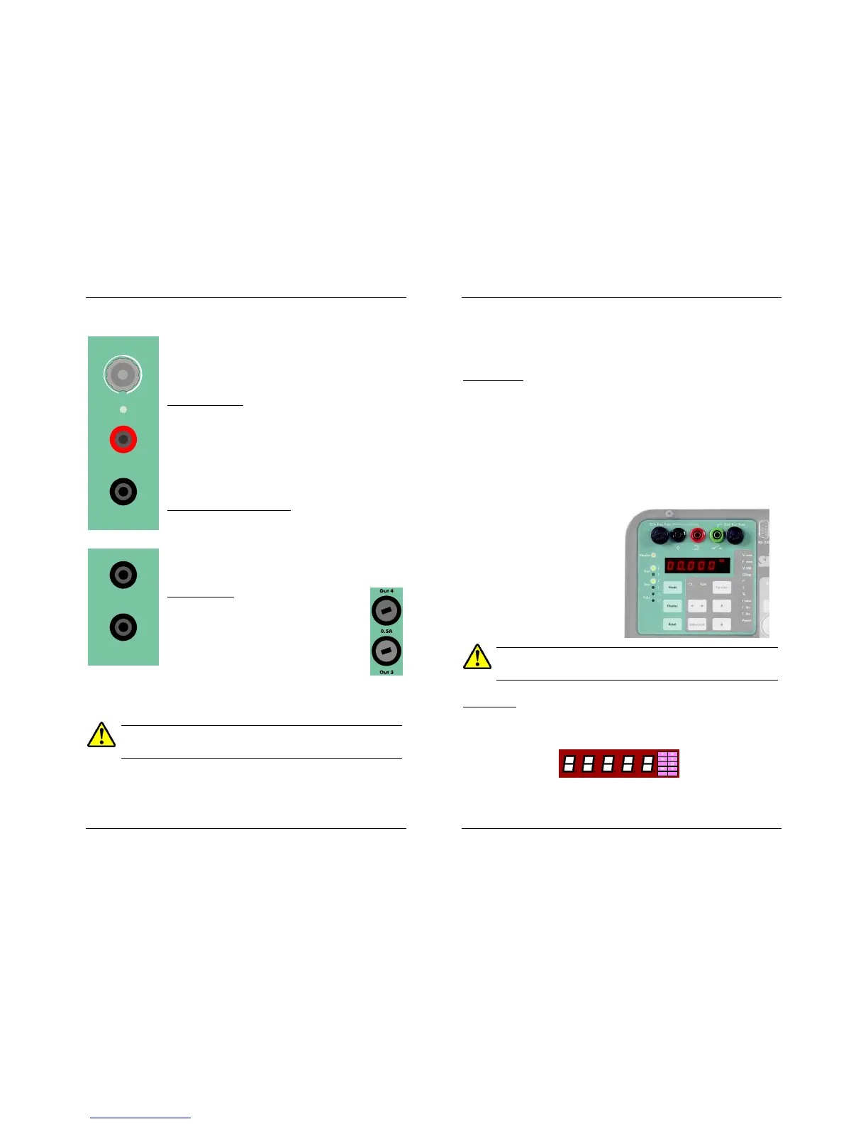
TIMER SECTION
The PTE-100-C’s digital Timer display is located on the left hand section of
the front panel, along with its control buttons and status LEDs.
Monitor Inputs
Tested relay’s operation is detected by means of two inputs:
1. A BLACK/GREEN input for dry (non-energized) contact monitoring,
and
2. A BLACK/RED input for voltage signals of up to 250 Vac or 250
Vdc maximum.
Both inputs are protected by 0.1 A FAST type 5x20 mm. fuses. Press and
turn the fuse holder 90º counter clockwise to replace a blown fuse.
REPLACE BLOWN FUSES WITH IDENTICAL ONES ONLY. DAMAGE
RESULTING FROM INCORRECT FUSE REPLACEMENT IS NOT COVERED
BY THE WARRANTY
Time Display
Time values resulting from tests are shown in Display #1 with a maximum
resolution of 1 millisecond.
Display #1 is a multi-function display. Besides time values in seconds or
cycles of the AC supply line, it can show various measurement units that are
automatically labeled at its right hand edge:

 Loading...
