PTE-100-C
9
The same micro-controller processes all the user’s control actions like output
on/off, the timer activation, the selection and display of function values, and
the protective alarms.
USER’S MANUAL
10
DESCRIPTION
All the elements in the front panel of the PTE-100-C are thoroughly de-
scribed here. In-depth explanation of their use is given in the Operation
section.
Many buttons, namely those that perform a different function when held down,
effectively actuate when released, rather than when pressed. These buttons will
produce a “secondary function” when pressed until an audible beep is heard.
We will now describe the PTE-100-C along the following sections:
MAIN AC SUPPLY
POWER OUTPUT SECTION
AUXILIARY VOLTAGE
TIMER SECTION
SPECIAL FUNCTIONS
COMMUNICATIONS
MAIN AC SUPPLY
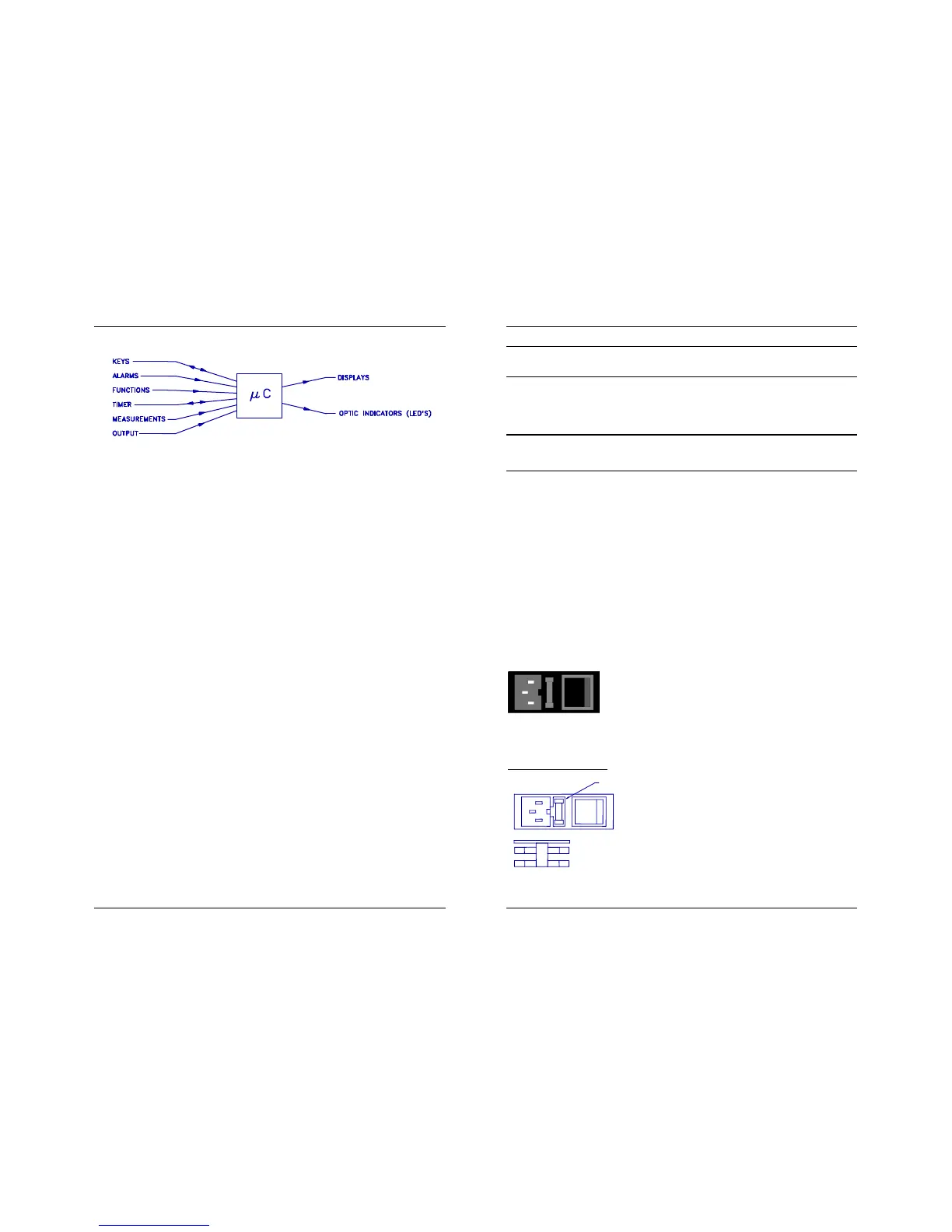
An AC supply block at the lower left-hand corner of
the front panel groups the power cord plug, a fuse
holder and the main on/off switch. Internal filters
prevent most AC perturbations from leaking into the
unit. The OFF position is indicated by a tiny circle in one of the faces of the
main switch.
Main Protection Fuses
The active (12A, Fast) fuse and a spare fuse
are included in the fuse holder. All the fuses
accessible from the front panel are standard,
5x20 mm cylindrical, and their current rating
and type are clearly printed.
SPARE FUSE
ACTIVE FUSE
FUSE
 Loading...

