REPLACE BLOWN FUSES WITH IDENTICAL ONES ONLY. DAMAGE
RESULTING FROM INCORRECT FUSE REPLACEMENT IS NOT COVERED
BY THE WARRANTY.
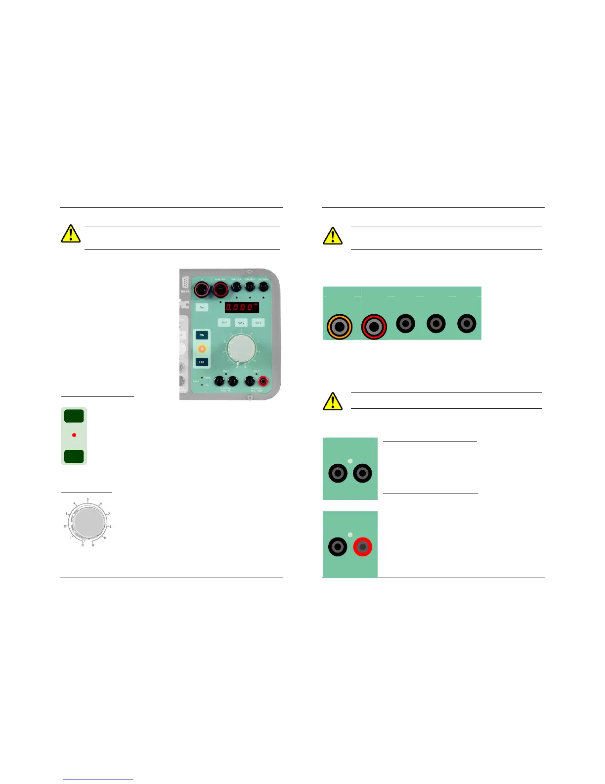
POWER OUTPUT SECTION
This is the right-hand section of the
front panel. It contains the main out-
put control buttons, the regulation
variac, the Display #2, the current
and voltage output taps, the tap selec-
tor, the displayed output selector and
a few associated and alarm LEDs:
Output ON/OFF buttons
These buttons connect and disconnect the main power ouput,
i.e. the current output taps and the Out 1 and Out 2 voltage
taps. A red LED indicates the following output states:
OFF: The output has been intentionally switched off
ON: The output has been intentionally switched on
BLINK: The output has been switched off by the unit. This will
be further explained under the OPERATION section.
Regulation Variac
This knob controls the output level of the current and
voltage power taps. The numerical 0-10 round scale is
provided as a positional reference only. The actual
output level is shown in Display #2 and, at any given
regulator position, its value always depends on the
connected impedance. Regardless of the regulator’s
position, no power will be output when the output control switch is OFF.
Always handle this regulator with care.
ON
OFF
USER’S MANUAL
12
A harmful amount of current could be injected into the connected
load if you accidentally switch the output ON with the variac in a
position other than zero.
Current output taps
At the top of the power output section, four current injection taps are provid-
ed to adapt the
current output
characteristics to
the connected
load, as well as to
facilitate the output
level regulation.
Tap zero is the common reference. If you are testing with currents ranging
from 0 to 50 A AC, for example, connect the load between the common
tap and the tap labeled “50 A / 20 V”. If you are using 4 mm bananas, you
will need the supplied 6-mm to 4-mm plug adapters for the common tap
and the 100 A tap.
Press these adapters all the way down before pulling them up for
removal.
0-250 VAC voltage tap (OUT 1)
Out 1 is located on the left immediately underneath the
variac knob. Output from this tap is measured and
regulated in AC volts. Maximum throughput current is
4A in non-continuous service.
0-350 VDC voltage tap (OUT 2)
Out 2 is located on the right of Out 1. Its output is
measured and regulated in DC volts. Polarity is indicat-
ed by the black (negative) and red (positive) plug col-
ors.
A standard 19 mm plug can be used with this pair of
connectors. All these taps and connectors comply to
the latest international standards and electrical safety
regulations.
0 100A/10V

 Loading...
