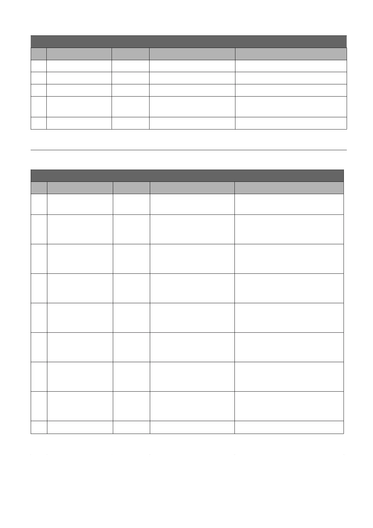
K1 connector pin-out for AC-M1 : DRIVE application
Pin Name I/O Specification Function
18 GND Negative logic supply
19 FAN output Low side 1,5A FAN command
20 OUT1 output Low side 1,5A Reserve command
21 +12V
auxiliary
supply
12V 300mAmax 12V supply
22 GND CAN CAN- bus negative supply
23 CAN-L I/O CAN-bus
L line input for CAN (No internal
termination resistor)
K2 connector pin-out for AC-M1 : DRIVE application
Pin Name I/O Specification Function
1 +5E
auxiliary
supply
5V+/-5%
200mAmax
5V supply
2
digital
input
20mA pull-up,
VL<=1V,
VH>=3,5V
Reserve
3
digital
input
20mA pull-up,
VL<=1V,
VH>=3,5V
Reserve
4 ENC.B1
digital
input
20mA pull-up,
VL<=1V,
VH>=3,5V
Phase B signal of the sensor
bearing mounted in the AC
right drive motor.
5 ENC.A1
digital
input
20mA pull-up,
VL<=1V,
VH>=3,5V
Phase A signal of the sensor
bearing mounted in the AC
right drive motor.
6
digital
input
4mA pull-up,
VL<=1V,
VH>=3,5V
Reserve
7
digital
input
4mA pull-up,
VL<=1V,
VH>=3,5V
Reserve
8
digital
input
4mA pull-up,
VL<=1V,
VH>=3,5V
Reserve
9 GND ENC Negative logic supply
10
analogue
input
Pull-up Reserve
PRELIMINARY VERSION 18
 Loading...