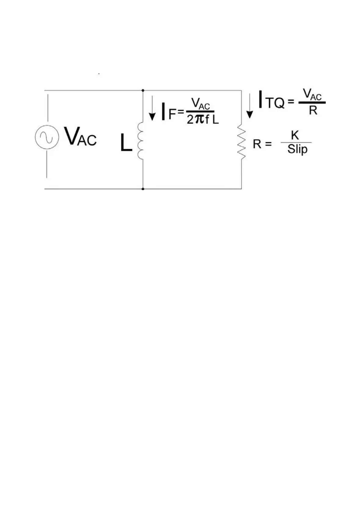
9.3.3 Electrical model
From an electrical point of view, an AC motor is a load which can be represented, in a fairly
simplified and non-exhaustive model, as the network in figure 12 ( the real equivalent
model is more complex).
The strength of the rotating magnetic field is proportional to I
F
, the current flowing through
the magnetizing inductance L.
I
F
is a mathematical aid which is used to describe the magnetic energy which is stored in
the motor and is therefore known as magnetizing current. The value of L depends on the
design of the motor.
Current flows through L is proportional to the voltage applied and inversely proportional to
the frequency.
The torque produced by the motor is proportional to the slip. Increasing the slip decreases
R, the rotor’s equivalent resistance seen by the stator.
Current I
TQ
is dependent on both the value of resistance R and the voltage input. Power
consumed/regenerated by the rotor is mostly active power.
I
F
and I
TQ
can both be set by controlling the frequency and the magnitude of V
AC
, the
voltage applied to the motor’s stator winding.
It is desirable to maintain I
F
at a constant value which produces maximum field strength in
the motor’s magnetic circuit, while varying I
TQ
to satisfy the changing torque requirement.
Maintaining constant I
F
requires the ratio of V
AC
/f be held constant.
As motor speed increases, the frequency f increases proportionally: until a point is
reached (typically the nominal speed) where V
AC
cannot be increased further (for example,
because it has reached the maximum allowable voltage supplied by the batteries). and
V
AC
/f can no longer be held constant.
Then, above the nominal speed, the controller is forced to limit the flux and, as a result, the
output torque is lessened too.
However, the controller is able to partially counteract this torque reduction by increasing
the slip, thus allowing the motor to be efficiently even at speeds higher than the rated one.
PRELIMINARY VERSION 53
Figure 12: Simplified electrical model of an AC induction motor.