3.4 List of complete pin-out
3.4.1 AC-M1 pin-out for PUMP application
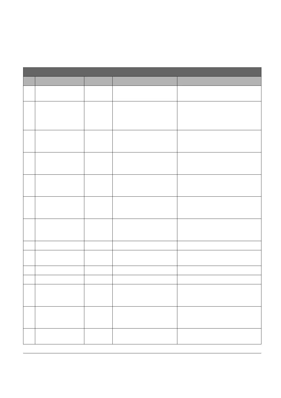
K1 connector pin-out for AC-M1 : PUMP application
Pin Name I/O Specification Function
1 +KEY (B)
Supply
input
Rated battery +25/-30%,
6Amax
Positive supply of the control
section of the AC-M1
2
digital
input
4mA pull-up,
VL<=1V,
VH>=3,5V
Reserve
3
digital
input
4mA pull-up,
VL<=1V,
VH>=3,5V
Reserve
4
digital
input
4mA pull-up,
VL<=1V,
VH>=3,5V
Reserve
5
digital
input
4mA pull-up,
VL<=1V,
VH>=3,5V
Reserve
6 TILT
digital
input
4mA pull-up,
VL<=1V,
VH>=3,5V
Tilt request
7 SIDE SHIFT
digital
input
4mA pull-up,
VL<=1V,
VH>=3,5V
Side shift request
8 BUZZER output Low side 0,5A Buzzer command
9 COMMON
Positive
output
High side 5A max Positive common
10 RX Input Diagnosis interface
11 TX Out Diagnosis interface
12
digital
input
4mA pull-up,
VL<=1V,
VH>=3,5V
Reserve
13
digital
input
4mA pull-up,
VL<=1V,
VH>=3,5V
Reserve
14 LIN I/O 12mA pull-up
LIN display connection or LED
diagnosis
15 CAN-H I/O CAN-bus H line input for CAN (No internal
PRELIMINARY VERSION 14
 Loading...