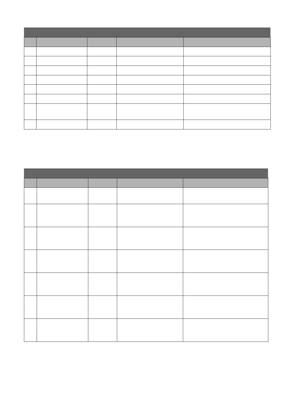
K1 connector pin-out for AC-M1 : PUMP application
Pin Name I/O Specification Function
termination resistor)
16 output Low side 2A Reserve command
17 output Low side 1,5A Reserve command
18 GND Negative logic supply
19 FAN output Low side 1,5A FAN command
20 OUT1 output Low side 1,5A Reserve command
21 +12V
auxiliary
supply
12V 300mAmax 12V supply
22 GND CAN CAN- bus negative supply
23 CAN-L I/O CAN-bus
L line input for CAN (No internal
termination resistor)
K2 connector pin-out for AC-M1 : PUMP application
Pin Name I/O Specification Function
1 +5E
auxiliary
supply
5V+/-5%
200mAmax
5V supply
2
digital
input
20mA pull-up,
VL<=1V,
VH>=3,5V
Reserve
3
digital
input
20mA pull-up,
VL<=1V,
VH>=3,5V
Reserve
4 ENC.B1
digital
input
20mA pull-up,
VL<=1V,
VH>=3,5V
Phase B signal of the sensor
bearing mounted in the AC
pump motor.
5 ENC.A1
digital
input
20mA pull-up,
VL<=1V,
VH>=3,5V
Phase A signal of the sensor
bearing mounted in the AC
pump motor.
6
digital
input
4mA pull-up,
VL<=1V,
VH>=3,5V
Reserve
7
digital
input
4mA pull-up,
VL<=1V,
VH>=3,5V
Reserve
8 LIFT
digital
input
4mA pull-up,
VL<=1V,
VH>=3,5V
Max LIFT speed request
PRELIMINARY VERSION 15
 Loading...