27
6.2.6
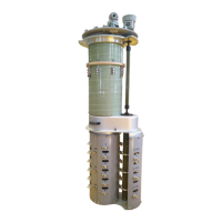
Installation of switch insert.
a. Make sure that the tap selector and the bottom connector are in the setting position when installing the
switch insert, and roughly align with the small end position of the connector; (see Figure-6-16)
b. Lift the switch insert to be above the oil compartment, and slowly drop the insert to its final position. (Use
10 pieces of M8 nuts, 13mm wrench, torque 12 to 15 N.m., with spring washer).
图
-19
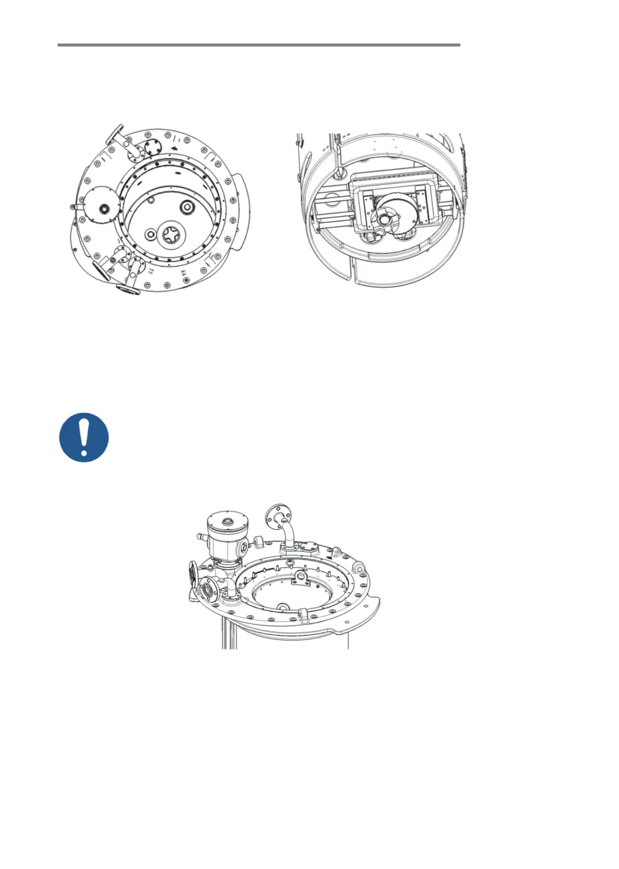
3. If there is a gap between the lower surface of the flange ring and the positioning surface of the bell-
type flange, serious problems will occur such as tap changer not operating, position disorder and so on!
1. After installation of the switch insert, carefully check its flange ring’s lower
surface and the bell-type flange’s positioning surface are pressed without gap;
2. Draw a red line on the upper surface of the switch insert’s flange ring. After
installation, the upper surface of the flange ring shall not exceed the red line.
See Figure-6-17.