43
9.6.2.6 Pull up the protective cover HM817.301 to the lower end of the square gear box, and set it on the
bushing HM8210.303.3, with the 3 notches facing directly,3 cylindrical pins, and then rotate the protective
cover so that the cylindrical pins are just stuck in the horizontal groove (see Figure-9-11). (3 pins are only for
temporary hang)
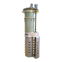
9.6.2.7 At this time, the two protective covers have been positioned, use two clamps on the thinner protective
cover (HM8170.302) at the bottom. Clamp the thicker protective cover (HM8170.301) on the upper part (see
Figure-9-12)
Figure-9-11 Figure-9-12
9.7 Installation of three single phase Tap changer
Attention: the arrangement of three single phase tap changers on one transformer, since it will cause the
operation of the diverter switch during the adjustment of gear box, so after adjustment, must check if each
diverter switch is on same position and they has simultaneous action when operated by hand crank.
9.8 Tap position calibration of tap-changer transmission system
Manual operation for one cycle before electric operation is required when the tap changer is connected to the
electric mechanism
The time interval between the moment the switch is switched to the completion of the motor-driven
mechanism is required to be the same for the two rotation directions When the tap changer is connected to the
motor-driven mechanism
The connection verification of the tap changer and the motor-drive mechanism normally has been performed
before the factory test. But in order to ensure the reliability of the tap changer, below procedure shall be
applied for the connection verification.
a. Rotate in the 1→N direction. When the switch is activated (when you hear the switch sound, continue to
turn the handle and record the number of rotations, until the red center mark in the green band on the tap
change operation indicator wheel of the electric mechanism appears in the middle of the observation window.
Stop shaking at the time, and write down the number of rotation m
b. Shake the handle in the opposite direction N→1 to return to the original setting position, and also record the
number of rotation K ( follow item 1 instruction)